GV60 TROUBLESHOOTING MANUAL
RESPONDING TO ALARMS
VERSION 1.0 2018-01-01
PAGE 4.1.49
Module Cooling Fan Replacement
.
1.
Remove the RF power module’s right-hand side cover by removing the 11 M3 countersunk screws.
Retain hardware for re-installation.
2.
Disconnect the suspect cooling fan’s mating plug (B1P1 through B6P1). Cut the tyrap that secures
the fan wiring to the splitter PWB.
3.
Remove and retain the cooling fan’s two M3 captive screws that secure the fan to the module.
4.
Obtain a replacement fan (Nautel Part # ZAP50) from the site spares kit or station spares kit or
from a suitable equivalent (vendor part # is Minebea Motor Mfg. Corp. 3115RL-07W-B79-E51).
5.
Install the replacement fan using retained screws. Torque hardware to 1.0 inch-pounds only to
avoid cracking the fan’s body. Twist the fan’s mating plug three times (reduces RFI) and reconnect
it to the splitter PWB. Secure the wiring using a tyrap (Nautel Part # HT66) from the ancillary kit.
6.
Re-install the right-hand side cover using retained hardware.
7.
Return the RF power module to the transmitter (see
“Installing an RF Power Module” on
).
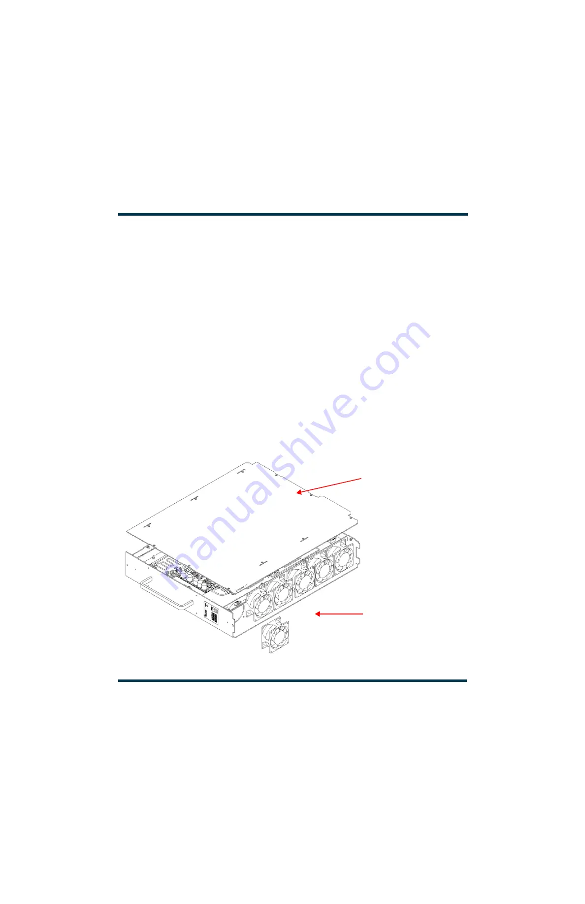
Figure 4.1.14: Replacing a Power Module Cooling Fan
COOLING FANS
B1 - B6
(B1 removed)
B1
B2
B3
B4
B5
B6
RIGHT-HAND
SIDE COVER
Содержание GV60
Страница 2: ......
Страница 4: ......
Страница 8: ...GV60 TROUBLESHOOTING MANUAL PAGE 4 VIII VERSION 1 0 2018 01 01 ...
Страница 102: ...GV60 TROUBLESHOOTING MANUAL PARTS LISTS PAGE 4 2 12 VERSION 1 0 2018 01 01 ...
Страница 463: ...VERSION 1 0 2018 01 01 MD 17 Figure MD 17 NAPA31C Power Amplifier PWB Q1 ...
Страница 466: ...VERSION 1 0 2018 01 01 MD 20 Figure MD 20 NAI23A RF Drive Splitter Changeover Assembly FRONT BACK ...
Страница 473: ...VERSION 1 0 2018 01 01 MD 27 Figure MD 27 NAL17 4 Input Reject Load Assembly TOP VIEW END VIEW 2 INPUT REJECT PWB A1 ...
Страница 475: ...GV60 TROUBLESHOOTING MANUAL LIST OF TERMS PAGE 4 6 2 VERSION 1 0 2018 01 01 ...
Страница 476: ......


