


33
CONDENSATE DRAIN/NEUTRALIZER
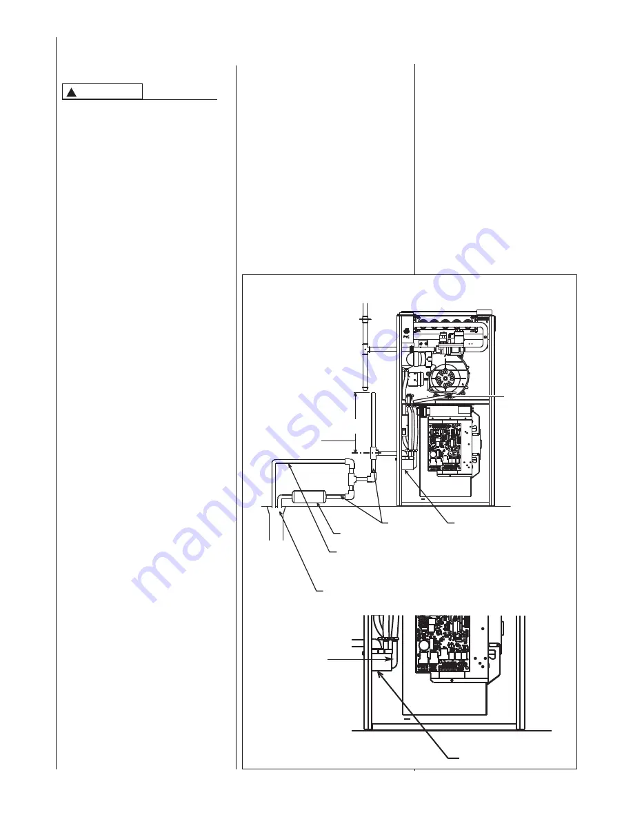
FIGURE 29
UPFLOW CONDENSATE DRAIN
GENERAL INFORMATION
DO NOT RUN DRAIN OUTDOORS.
FREEZING OF CONDENSATE CAN
CAUSE PROPERTY DAMAGE.
IMPORTANT:
Do not connect into a
common drain line with an air con-
ditioner evaporator coil drain. A blocked
or restricted drain line can result in
over-flow of the coil pan and negate the
furnace blocked drain shutoff control.
FILL TRAP ASSEMBLY WITH
WATER BEFORE OPERATING THE
FURNACE.
This can be done by
removing the drain hose
from the trap and pouring about a
cup of water into the vent trap. Water
will flow into the house drain when the
trap is full.
If local codes require, install a
condensate neutralizer cartridge in the
drain line. Install cartridge in horizontal
position only. Also install an overflow
line if routing to a floor drain. See 29.
If no floor drain is available, install a
condensate pump that is resistant to
acidic water. Pumps are available from
your local distributor. If pump used is
not resistant to acidic water, a
condensate neutralizer must be used
ahead of the pump. The condensate
pump must have an auxiliary safety
switch to prevent operation of the
furnace and resulting overflow of
condensate in the event of pump
failure. The safety switch must be wired
through the “R” circuit only (low voltage)
to provide operation in either heating or
cooling modes.
UPFLOW MODELS
The condensate drain trap is located in
the blower compartment on the left-
hand side of the jacket. A short piece of
1
/
2
-in. PVC pipe and a
1
/
2
-in. tee are
provided. Connect the
1
/
2
-in. pipe to the
elbow on the trap and the tee to this
pipe so that the open end is upward.
Run a drain tube from the bottom of the
tee to a floor drain or condensate
pump.
IMPORTANT:
The upflow model only
has a new drain system. There is a third
port on the drain trap (marked by a red
cap) for the hose attached to the
induced draft motor. Remove plug in
inducer drain hose and remove cap off
drain trap before connecting inducer
drain hose to drain trap. All three hoses
MUST be attached during operation of
the furnace. Be sure all three hoses are
secured to the drain trap using the hose
clamps provided in the parts bag.
IMPORTANT:
If installing the unit over
a finished ceiling or living area, be
certain to install an auxiliary condensate
drain pan under the entire unit
extending out under the condensate
tee.
IMPORTANT:
There are two options
when choosing a height for the
condensate riser:
CONDENSATE OVERFLOW: With a 5
inch riser installed above the tee, a
blocked drain will result in overflow from
the riser.
FURNACE SHUTDOWN: To cause the
furnace to shut down when a blocked
drain is present, install a riser which is a
minimum of 10
13
/
16
“. If the furnace is
installed in an attic, crawlspace or other
area where freezing temperatures may
occur, the furnace drain can freeze
while shut off for long periods of time.
Use a solvent cement that is
compatible with PVC material. Cut the
drain hoses to the appropriate length
and connect to the trap with hose
clamps. Tighten the clamps with
pliers and check for leaks after
attaching.
IMPORTANT:
The inducer drain hose
must slant downward away from
inducer. If the hose is not slanted,
the inducer will fill with water and
cause the pressure switch to open,
causing nuisance failures or
intermittent operation.
!
CAUTION
I408
10
13
/
16
CONDENSATE TRAP
TO FLOOR DRAIN OR CONDENSATE PUMP
OVERFLOW LINE
(REQUIRED ONLY WHEN
OPTIONAL NEUTRALIZER
CARTRIDGE IS USED.)
DRAIN LINE
NEUTRALIZER CARTRIDGE (OPTIONAL)
NOTE:
SEE UPFLOW MODEL
NOTES FOR PIPE
HEIGHT
NOTE: CONNECT
INDUCER DRAIN HOSE
TO SMALLER PORT ON
CONDENSATE TRAP.
NOTE: INDUCER
DRAIN HOSE
MUST SLANT
DOWNWARD
AWAY FROM
INDUCER.
CONDENSATE TRAP


