background image

Installation 


21


Connect the Power Supply 

WARNINGS


1. 

MAINS


SUPPLY


VOLTAGES


(220

240


V


AC)


ARE


PRESENT


IN


THIS


EQUIPMENT


WHICH


MAY


CAUSE


DEATH


OR


SERIOUS


INJURY


BY


ELECTRIC


SHOCK.


ONLY


A


QUALIFIED


ELECTRICIAN


OR


INSTALLER


SHOULD


CONNECT


THE


POWER


SUPPLY


TO


THIS


UNIT.


2.


THIS


UNIT


MUST


BE


CORRECTLY


EARTHED.


This


unit


is


designed


for


operation


from


a


single

phase


alternating


current


source


(220

240


V


AC).


A


1.5


m


cable


is


connected


internally


to


the


unit


for


connection


to


a


switched


fused


spur.


To


connect


the


power


supply:


1.


Ensure


the


local


AC


power


supply


is


switched


off.


2.


One


end


of


the


power


cable


supplied


is


already


connected


to


the


unit


and


routed


through


the


Cable


Inlet


Plate


via


a


suitable


gland


to


ensure


the


IP


rating


of


the


unit


is


not


affected.


3.


Connect


the


other


end


of


the


cable


to


the


switched


fused


spur.


4.


Use


cable


clamps


and


clips


to


secure


the


cable,


as


appropriate.


Connecting a Boost (Light) Switch 

A


Switched


Live


(LS1


or


LS2)


may


be


used


to


boost


the


airflow


when


a


light


is


turned


on,


for


instance


in


a


bathroom


or


kitchen.


Note


that


the


LS2


connection


has


a


boost


start


time


delay


of


5


minutes.


In


the


event


that


the


unit


is


inadvertently


left


running


on


boost,


it


will


revert


to


normal


speed


after


2


hours.


Power


supplied


to


the


unit


via


the


LS1


or


LS2


connections


must


be


supplied


via


the


same


circuit


as


the


incoming


L


mains


as


indicated


on


p20.

Содержание Monsoon MON-HRU/230-100

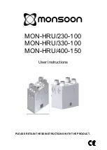
Страница 1: ...MON HRU 230 100 MON HRU 330 100 MON HRU 400 150 Installation Commissioning PLEASE RETAIN THESE INSTRUCTIONS WITH THE PRODUCT...

Страница 2: ...ervised to ensure that they do not play with the appliance INSTALLATION GUIDANCE 1 The installer is responsible for the installation and electrical connection of the MON HRU system on site It is the r...

Страница 3: ...ol 24 Maintenance 26 Filter Maintenance 26 12 Monthly Maintenance 26 PRODUCT FICHE 27 UK Building Regulations Part F Declaration of Conformance MON HRU 230 100 AND MON HRU 400 150 units conform to the...

Страница 4: ...igned for continuous 24 hour exhaust ventilation of stale moist air from bathrooms toilets and kitchens As the stale air is extracted a heat exchanger within the unit transfers up to 94 of the heat an...

Страница 5: ...le phase 220 240 V AC single phase 220 240 V AC single phase AC Frequency Input 50 Hz nominal 50 Hz nominal 50 Hz nominal Rated Power 150 W max 160 W max 190 W max Physical Height excluding spigots 55...

Страница 6: ...Installation 6 Figure 4 MON HRU 400 150 Dimensions MON HRU 230 100 Performance graph for Vertical Discharge Note Graph show 2 typical system curves with total unit input power in Watts...

Страница 7: ...HRU 330 100 Performance graph for Vertical and Horizontal Discharge MON HRU 400 150 Performance graph for Vertical and Horizontal Discharge Note Graph show 2 typical system curves with total unit inp...

Страница 8: ...ppropriate lifting techniques and appliances when moving heavy equipment Check Site Requirements and Safety Notices Check that the physical and environmental conditions for the site meet or exceed the...

Страница 9: ...w the unit to be installed in the opposite orientation Installing the Unit in the Opposite Orientation LH Condensate Installing the unit in the opposite orientation involves removing the front cover a...

Страница 10: ...onnect the connection looms 7 Disconnect all the wiring looms from control panel 8 Remove the 2 screws and detach the rear Cable Inlet Plate Note that the grommets shown may be replaced by easy knock...

Страница 11: ...on continue on page 11 or for horizontal discharge condensate connection go to page 12 Vertical Discharge Condensate Installation Note The 22 mm diameter condensate pipe is suitable for standard 22 mm...

Страница 12: ...e there is a minimum 3 degree fall to allow condensate drainage Both left hand and right hand condensate drain pipes are supplied for use as appropriate depending on the orientation of the unit 4 Go t...

Страница 13: ...L MOUNTING on pages 15 to 18 for information on marking out the wall for the position of the condensate drain and wall mounting brackets Fit Vertical discharge 32mm waste pipe fitted with 22 32mm redu...

Страница 14: ...the spigots 1 Remove the spigot by unscrewing the screw s securing it to the chassis Then pull the spigot firmly from the entry exit hole 2 Remove the blanking cap by unscrewing the screw s securing i...

Страница 15: ...ow of screws 3 Mark the condensate and wall bracket positions 4 Fit the stand off feet in place supplied in the accessory bag 5 Fit metal wall bracket supplied to the wall using appropriate fixings 6...

Страница 16: ...Installation 16 MON HRU 230 100 MON HRU 330 100 Wall Mounting Dimensions...

Страница 17: ...and wall bracket positions using the drawing below 4 Fit metal wall bracket supplied to the wall using appropriate fixings 5 Fit the stand off feet in place supplied in the accessory bag 6 Lift unit...

Страница 18: ...Installation 18 MON HRU 400 150 Wall Mounting Dimensions...

Страница 19: ...uct 100 150 mm long extended to its full length when connecting to ductwork 2 Securely connect this ducting to the spigots using worm drive clips cable ties or duct tape 3 Insulate any ducting passing...

Страница 20: ...on the control unit may be used Table 1 Mains Cable Connections Terminal No Name Cable connection Description L Mains Live Brown 220 240 V AC 50 Hz input N Mains Neutral Blue 220 240 V AC 50 Hz input...

Страница 21: ...the power cable supplied is already connected to the unit and routed through the Cable Inlet Plate via a suitable gland to ensure the IP rating of the unit is not affected 3 Connect the other end of t...

Страница 22: ...olator feeding the unit and the fan motors will start N B If you are intending to carry out work or maintenance inside the unit switch off the power at the mains outlet supplying the unit before you r...

Страница 23: ...ning the unit Ensure that the system is installed according to the system designers intent incorporating any acoustic ducting that all joints are air tight ducting is well supported bends are avoided...

Страница 24: ...to suit Figure 5 MON HRU Controls Summer Mode The unit is equipped with a Summer Mode for use when the indoor temperature is higher than desired and the outdoor temperature is lower than the indoor te...

Страница 25: ...oost mode Press once again to exit Boost mode To activate Summer Mode press 3 times in less than three seconds after a short pause the green LED will illuminate and the supply fan will stop To exit Su...

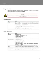
Страница 26: ...for 10 seconds 12 Monthly Maintenance Item Action Fan Filters Change the Fan Filters 1 Open the filter flaps and remove the 2 filters 2 Insert the replacement filters 3 Close the filter flaps 4 Reset...

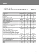
Страница 27: ...Appendix 27 PRODUCT FICHE For Residential Ventilation Units Complying Commission Delegated Regulation EU No 1254 2014...

Страница 28: ...National Ventilation Stathe Road Burrowbridge Somerset TA7 0RY Website www nationalventilation co uk email info nvagroup co uk Sales and technical hotline 01823 690290 475018 E 1018...

Страница 29: ...MON HRU 230 100 MON HRU 330 100 MON HRU 400 150 User Instructions PLEASE RETAIN THESE INSTRUCTIONS WITH THE PRODUCT...

Страница 30: ...not attempt to remove the covers of this unit High Voltage is present in this unit NEW PROPERTY FILTER MAINTENANCE When fitted to a new build property the supply and exhaust filters should be checked...

Страница 31: ...the Building Regulations document F 2010 The unit is designed for continuous 24 hour exhaust ventilation of stale moist air from bathrooms toilets and kitchens As the stale air is extracted a heat ex...

Страница 32: ...20 240 V AC single phase 220 240 V AC single phase 220 240 V AC single phase AC Frequency Input 50 Hz nominal 50 Hz nominal 50 Hz nominal Rated Power 150 W max 160 W max 190 W max Physical Height excl...

Страница 33: ...onitoring 5 Powering Up the Unit Switching On 1 Switch on the power at the mains supply isolator feeding the unit and the fan motors will start Switching Off 2 Turn the power off at the mains supply i...

Страница 34: ...peration A label will have been applied by the person setting the flow rates during the commissioning process The label is applied to the area indicated by the printed corners and is intended to maint...

Страница 35: ...Maintenance Item Action Fan Filters Change the Fan Filters 1 Open the filter flaps and remove the 2 filters 2 Insert the replacement filters 3 Close the filter flaps 4 Reset the LED press and hold th...

Страница 36: ...National Ventilation Stathe Road Burrowbridge Somerset TA7 0RY Website www nationalventilation co uk email info nvagroup co uk Sales and technical hotline 01823 690290 475021C 0618...

Отзывы: