


Chapter 3
NI-VXI Software Installation and Configuration
© National Instruments Corporation
3-7
VXI-AT2022/NI-VXI SCO UNIX Getting Started
Logical Address Configuration
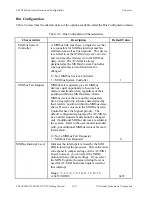
Table 3-1 describes the characteristics of the options available under the Logical Address
Configuration menu.
Table 3-1. Logical Address Configuration Characteristics
Characteristic
Description
Default Value
AT-MXI Base I/O
Address
Indicates the I/O Address of the AT-MXI
configuration registers. This value must
correspond to the selected jumper settings
on the board.
Range = 100h to 3E0h in increments of
20h (hex)
0x340
Master Window Base
A 64 KB memory-mapped I/O window, which
the AT-MXI board uses to access the VXIbus.
Range = A000h to E000h in increments of
1000h (hex)
0xD000
Address Space
Indicates the address spaces used by the
AT-MXI.
0 = A16/A24
3 = A16 only
3
Master DMA Channel
Indicates the DMA channel that the AT-MXI
uses to perform master-mode block transfers
onto the VXIbus. This value must correspond to
the jumper settings on the AT-MXI board. You
can select the NONE option with any setting.
Range = 0, 1, 2, 3, 5, 6, 7, or 0xff (NONE)
Note: This field is currently disabled.
0xff
AT-MXI Board
Interrupt Level
Indicates the interrupt level used by the board
to interrupt the processor. This value must
correspond to the jumper settings on the
AT-MXI board.
Range = 3, 4, 5, 6, 7, 9, 10, 11, 12, 14, or 15
12
(continues)