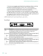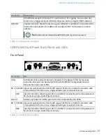
USRP-2945 Front Panel, Back Panel, and LEDs
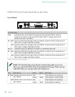
Front Panel
Connector Use
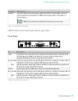
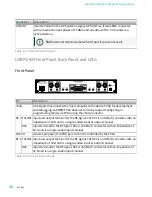
JTAG
A USB port that connects the host computer to the device FPGA for recovery
purposes. This port can be used with the Xilinx iMPACT configuration tool to
temporarily load a new bitfile.
RF 0 RX1 Input terminal for the RF signal. RX1 is an SMA (f) connector with an impedance of
50 Ω and is a single-ended input channel.
RX2 Input terminal for the RF signal. RX2 is an SMA (f) connector with an impedance of
50 Ω and is a single-ended input channel.
AUX I/O
General-purpose I/O (GPIO) port. AUX I/O is controlled by the FPGA.
RF 1 RX1 Input terminal for the RF signal. RX1 is an SMA (f) connector with an impedance of
50 Ω and is a single-ended input channel.
RX2 Input terminal for the RF signal. RX2 is an SMA (f) connector with an impedance of
50 Ω and is a single-ended input channel.
Table 14. Connector Descriptions
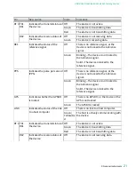
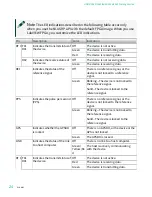
Note
The LED indications described in the following table occur only
when you use the NI-USRP API with the default API image. When you use
LabVIEW FPGA, you customize the LED indications.
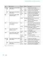
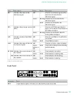
LED
Description
Color
State
Indication
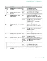
RF 0 RX1 Indicates the receive status of
the module.
OFF
—
The module is not receiving.
Green
Solid
The module is receiving data.
RX2 Indicates the receive status of
the module.
OFF
—
The module is not receiving.
Green
Solid
The module is receiving.
ni.com
32
USRP-2940/2942/2943/2944/2945 Getting Started

