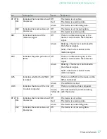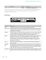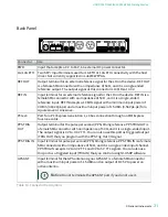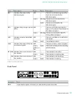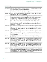
Connector
Description
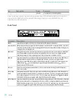
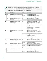
GPS ANT
Input terminal for the GPS antenna signal. GPS ANT is a female SMA connector
with a maximum input power of 15 dBm and an output of DC 5 V to power an
active antenna.
Notice
Do not terminate the GPS ANT port if you do not use it.
Table 10. Connector Descriptions
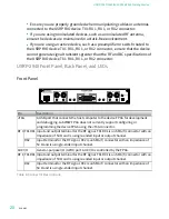
USRP-2943 Front Panel, Back Panel, and LEDs
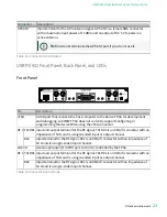
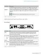
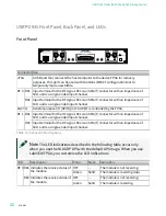
Front Panel
LINK
TX OUTPUT MAX +20 dBm, RX INPUT MAX -15 dBm, ALL RF PORTS 50 Ω
TX1 RX1
RX2
GPS
PPS
REF
TX1 RX1
RX2
JTAG
PWR
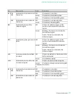
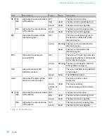
Pin
Description
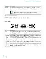
JTAG
A USB port that connects the host computer to the device FPGA for development
and debugging. LabVIEW FPGA does not currently support configuring or
programming the device FPGA using the JTAG connector.
RF 0 TX1 RX1 Input and output terminal for the RF signal. TX1 RX1 is an SMA (f) connector with an
impedance of 50 Ω and is a single-ended input or output channel.
RX2
Input terminal for the RF signal. RX2 is an SMA (f) connector with an impedance of
50 Ω and is a single-ended input channel.
AUX I/O
General-purpose I/O (GPIO) port. AUX I/O is controlled by the FPGA.
RF 1 TX1 RX1 Input and output terminal for the RF signal. TX1 RX1 is an SMA (f) connector with an
impedance of 50 Ω and is a single-ended input or output channel.
RX2
Input terminal for the RF signal. RX2 is an SMA (f) connector with an impedance of
50 Ω and is a single-ended input channel.
Table 8. Connector Descriptions
ni.com
26
USRP-2940/2942/2943/2944/2945 Getting Started

