


Chapter 3
Connecting the UMI-7774/7772 to Drives and Other Devices
©
National Instruments Corporation
3-27
National Instruments UMI-7774/7772 User Manual
General-Purpose Digital I/O
The UMI-7774/7772 routes 16 of the general-purpose digital I/O lines
of the National Instruments motion controller to a single 25-pin D-SUB
connector. All 16 digital I/O signals are optically isolated on the
UMI-7774/7772. These signals are configurable as inputs and/or outputs
on the National Instruments motion controller. Use MAX or NI-Motion
software to configure the bits on port 1 as inputs and the bits on port 2
as outputs.
The 8 bits from the first port on the motion controller (Port 1: bits 0–7)
become sinking inputs on the UMI-7774/7772, and the 8 bits from the
second port of the motion controller (Port 2: bits 0–7) become sourcing
outputs on the UMI-7774/7772. Refer to Figure 3-17 for the pin locations
of the Digital I/O connector and to Table 3-9 for the corresponding signals
for each pin. Refer to Figures 3-16 through 3-20 for information on how to
wire the digital inputs and outputs on the UMI-7774/7772.
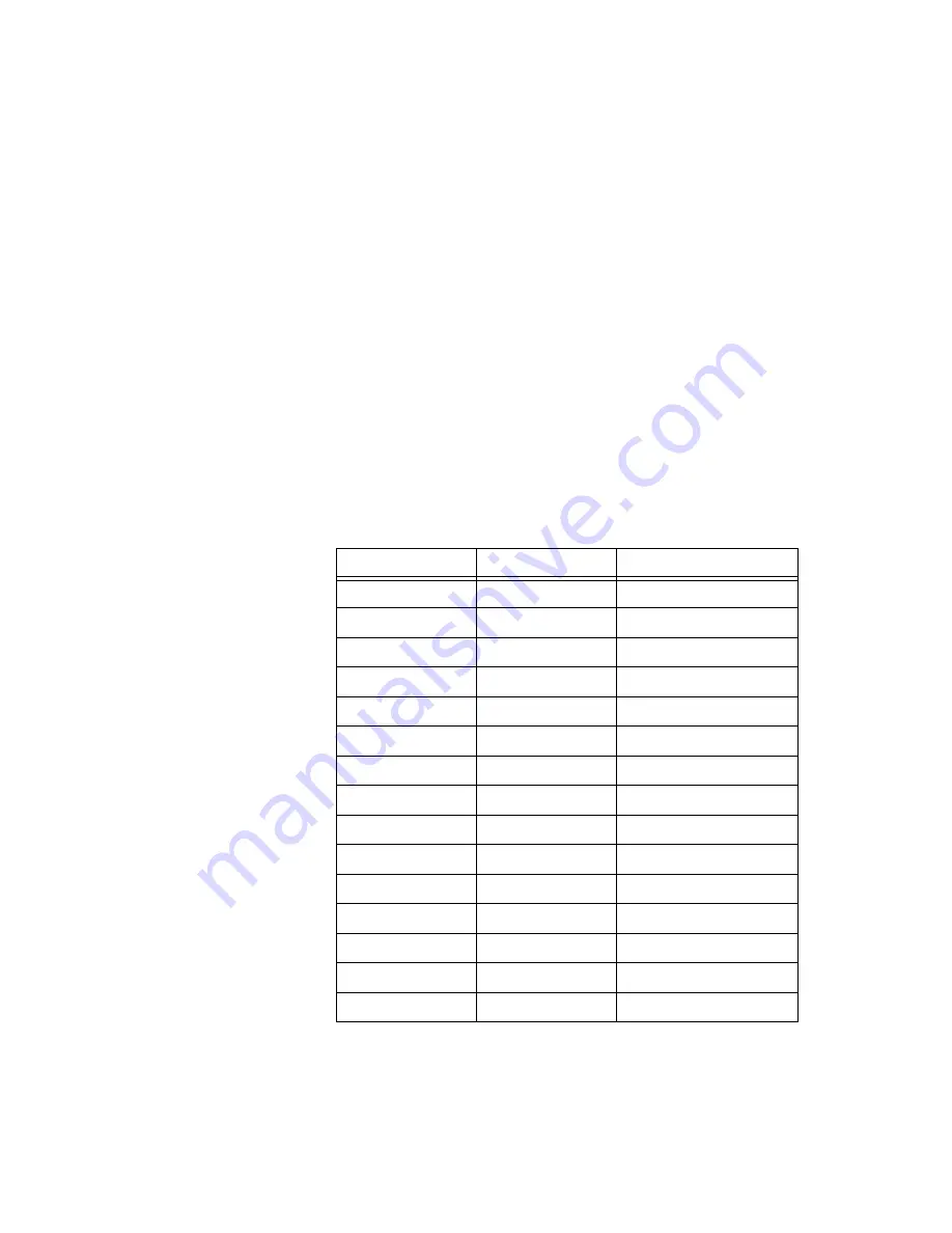
Table 3-9.
Digital I/O Connector Pin Assignment
Pin
Signal
Optically Isolated
1
Digital Input 0
Yes
2
Digital Input 2
Yes
3
Digital Input 4
Yes
4
Digital Input 6
Yes
5
Iso Power (Output)
Yes
6
Iso Power (Output)
Yes
7
NC
No
8
Digital Output 0
Yes
9
Digital Output 2
Yes
10
Digital Output 4
Yes
11
Digital Output 6
Yes
12
Iso Power (Output)
Yes
13
Iso Power (Output)
Yes
14
Digital Input 1
Yes
15
Digital Input 3
Yes


