


Chapter 3
Connecting the UMI-7774/7772 to Drives and Other Devices
National Instruments UMI-7774/7772 User Manual
3-12
ni.com
Note
You must configure the National Instruments motion controller Inhibit Out signals
as active-low for proper operation of the inhibit logic on the UMI-7774/7772.
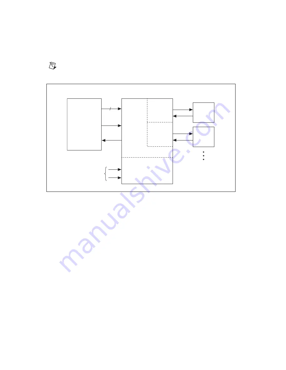
Figure 3-10.
Fault, Enable, and Global Stop Wiring Diagram
The Enable output circuit provides a current source to an external device.
The maximum output current when V
iso
is 30 V is 160 mA. The maximum
output current when V
iso
is 24 V is 150 mA. The maximum output current
when V
iso
is 5 V is 60 mA. The output voltage is within 1.2 V of the voltage
provided on the V
iso
power supply. Refer to Figure 3-11 for an illustration
of the Enable output interface circuit.
If you are connecting the Fault output to inductive loads, such as relays and
solenoids, special precautions may be necessary. Refer to the
Inductive
Loads Connected to UMI-7774/7772
section for more information.
Controller
Axis
Inhibit
Host Bus
Interlock
Shutdown
UMI-7774/7772
Motion I/O Connector
Axis 1
Enable
Fault
4
Axis 2
Enable
Fault
Drive 1
Drive 2
Global Stops
Shutdown
Inhibit_All
User Supplied