TC-2095 Terminal Block Calibration Procedure
4
ni.com
b.
Connect a test connector adapter to terminal A1 on the 96-pin
female DIN connector on the rear of the terminal block. Attach
the other end of this wire to the positive terminal of the +5 VDC
power supply.
c.
Connect a test connector adapter to terminal A2 on the 96-pin
female DIN connector on the rear of the terminal block. Attach
the other end of this wire to the negative terminal of the +5 VDC
power supply.
2.
Connect a calibrated DMM to the temperature-sensor output of the
terminal block.
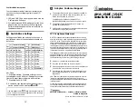
a.
Refer to Figure 2 to locate jumper W1 and verify that MTEMP
is jumpered on the terminal block.
Figure 2.
TC-2095 Terminal Block Parts Locator Diagram
1
Cover
2
Screws
3
CJC Sensor
4
DTEMP/MTEMP Jumper
5
W2 Jumper
5
4
1
2
3