


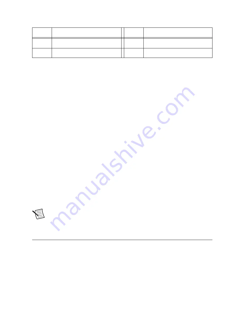
Table 38. J10 Feedback Connector Pinout (Continued)
Pin
Signal
Pin
Signal
11
Hall_1.2
23
GND
12
+5 V
24
+5 V
See the
LVTTL Lines
on page 38 section for more information on how feedback signals are
connected to the GPIC digital lines.
RS485 Input Signals
RS485 input signals are used for interfacing with a large selection of encoders. Differential
RS485 signals are connected between the Feedback_x.x_A and Feedback_x.x_B lines. Each
input line can support up to ±25 V fault voltage. In normal operating mode, the input voltage
should be kept within the RS485 specifications.
The outputs of the RS485 receivers are directed to the LVTTL lines. The name of the
corresponding LVTTL signal is
Feedback_x.x
. For details, refer to
LVTTL Lines
on page
38.
Hall Sensor Input Signals
Each of the six Hall sensor inputs are designed for open collector driving outputs. Each input
has a 10 kΩ pull-up resistor connected to +5 V. The inputs have a Schmitt trigger input circuit
that reduces the false transitions for a noisy input signal. The output of the Schmitt trigger
circuit is connected to the LVTTL signals. For details, refer to
LVTTL Lines
on page 38.
+5 V Output
The feedback connectors have an +5 V output that can be used for powering encoders. The
+5 V output is connected to the sbRIO-9687 internal rail and can supply up to 0.5 A for each
connector.
Note
A short circuit on the +5 V rail could shut down the sbRIO-9687 and may
require cycling the +24 V input.
Debug LEDs
The sbRIO-9687 interface board provides four LEDs for debugging purposes. One LED is
powered by the 5 V rails, and the others are driven by the LVTTL lines. The LED turns ON
when the corresponding LVTTL line is low. The following table provides information for each
LED, including reference indicator, color and LVTTL command line.
44
|
ni.com
|
sbRIO-9687 User Manual


