background image

Chapter 2

Installation and Configuration

NI PXI-1052 User Manual

2-18

ni.com

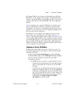
In LabWindows

/CVI

, select 

Tools»Create/Edit DAQmx 

Tasks

In Measurement Studio, open Visual Studio .NET and select 

Project»Add New Item

 to open the Add New Item dialog box. 

In the Categories pane, select 

Measurement Studio»Assistants

In the Templates pane, select 

DAQmx Task Class

.

Follow the online instructions to create a new task. 

1.

Select an I/O type, such as analog input.

2.

Select the measurement or generation to perform.

3.

Choose the sensor to use, if applicable.

4.

Select the channels to add to the task. You can add global channels to 
the task or select physical channels from which to create local channels 
in the task.

5.

Configure measurement-specific settings, timing, and triggering, 
if necessary. 

6.

Save the task.

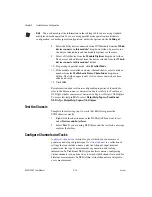
If you opened the DAQ Assistant from LabVIEW or 
LabWindows/CVI, click 

OK

If you opened the DAQ Assistant from Measurement Studio, 
select 

File»Save

You now can use the task in an application. Refer to the 

DAQ Assistant 

Help 

or application software documentation for more information about 

using a task or generating code.

Configure Global Channels for NI-DAQmx

Configure global channels with the DAQ Assistant when you use 
NI-DAQmx.

In MAX, right-click 

Data Neighborhood

 and select 

Create New

In the 

Create New

 window, select 

NI-DAQmx Global Channel 

and 

click 

Next

.

You also can open the DAQ Assistant directly from within 
LabVIEW 7.0 or later, LabWindows/CVI 7.0 or later, or 
Measurement Studio 7.0 or later. 

In LabVIEW, use the DAQmx Global Channel control to open the 
DAQ Assistant. Right-click the control and select 

New Channel 

(DAQ Assistant)

.

Содержание PXI NI PXI-1052

Страница 1: ...PXI NI PXI 1052 User Manual NI PXI 1052 User Manual April 2004 Edition Part Number 371087A 01...

Страница 2: ...41 31 30 Greece 30 2 10 42 96 427 India 91 80 51190000 Israel 972 0 3 6393737 Italy 39 02 413091 Japan 81 3 5472 2970 Korea 82 02 3451 3400 Malaysia 603 9131 0918 Mexico 001 800 010 0793 Netherlands 3...

Страница 3: ...on or maintenance instructions owner s modification of the product owner s abuse misuse or negligent acts and power failure or surges fire flood accident actions of third parties or other events outsi...

Страница 4: ...Trigger Slot 1 6 Peripheral Slots 1 6 Local Bus 1 7 SCXI Control Slot 1 7 Trigger Bus 1 7 System Reference Clock 1 8 SCXI Subsystem Overview 1 8 Chapter 2 Installation and Configuration Safety Informa...

Страница 5: ...assis 2 14 Configure the SCXI Modules 2 15 Test the Chassis 2 16 Configure Channels and Tasks 2 16 Configure a Task in NI DAQmx 2 17 Configure Global Channels for NI DAQmx 2 18 Remote Voltage Monitori...

Страница 6: ...rence document shipped with the product for precautions to take When symbol is marked on a product it denotes a warning advising you to take precautions to avoid electrical shock When symbol is marked...

Страница 7: ...oftware SCXI user manuals and installation guides Read these documents next for information about signal connections and module configuration They also explain in greater detail how the module works a...

Страница 8: ...tached components If damage appears to have been caused during shipment file a claim with the carrier Retain the packing material for possible inspection and or reshipment Caution Many components with...

Страница 9: ...ign that is optimized for use in a wide range of applications The PXI 1052 has a built in digital and analog bus between the PXI and SCXI subsystems that allows a DAQ DMM module in the fourth PXI slot...

Страница 10: ...eaker no AC input fuse to replace Remote PXI voltage monitoring and inhibit through a rear panel connector On Off Standby power switch on the front panel for easy access SCXI power switch on the chass...

Страница 11: ...Voltage Analog Bus Connector 5 SCXI High Voltage Analog Bus Connector 6 PXI Filler Panel 7 SCXI High Voltage Backplane 8 Removable Feet 9 SCXI Subsystem Backplane 10 SCXI Module Slots 11 PXI Peripher...

Страница 12: ...t used PXI 1052 Backplane Overview This section gives a basic hardware overview of the PXI 1052 backplane with interoperability information for the PXI 1052 with CompactPCI and general information abo...

Страница 13: ...B Pinouts for pinout information The PXI 1052 backplane has 5 V V I O Refer to the CompactPCI Specification PICMG 2 0 R3 0 for details regarding V I O System Controller Slot The system controller slot...

Страница 14: ...lity SCXI Control Slot Slot 4 of the PXI backplane has connections for a PXI peripheral module such as an NI PXI DAQ module an NI PXI DMM module or an NI Switch controller module to control the SCXI s...

Страница 15: ...igger slot Refer to Table B 4 P2 J2 Connector Pinout for the Star Trigger Slot Sourcing an external clock on this pin automatically overrides the 10 MHz source of the backplane Once the transition has...

Страница 16: ...the Connecting Safety Ground section for instructions on connecting safety ground Live Circuits Operating personnel and service personnel must not remove protective covers when operating or servicing...

Страница 17: ...ters through filters and fan inlets in the lower rear of the chassis and exits through the upper sections on both sides and through the top as shown in Figure 2 1 Provide adequate ventilation space ar...

Страница 18: ...g performance install optional PXI filler panels in unused slots Secure the panels with the captive mounting thumbscrews provided You can obtain these panels through NI Installing Slot Blockers You ca...

Страница 19: ...ation with a yellow stripe or must be noninsulated bare 2 Attach the opposite end of the wire to permanent earth ground using toothed washers or a toothed lug Connecting to Power Source Caution Do not...

Страница 20: ...ED is flashing green the air intake temperature has exceeded the chassis operating range Complete the following steps a Power off the system b Unplug the AC power cable c Inspect the chassis for venti...

Страница 21: ...while you install the controller Make sure the chassis power switch is in the Off Standby position Caution To protect yourself and the chassis from electrical hazards leave the chassis off until you c...

Страница 22: ...the keyboard mouse and monitor to the appropriate connectors Connect devices to ports as required by your system configuration 5 Power on the chassis Verify that the controller boots If the controlle...

Страница 23: ...chassis are not lit 2 Install a module into a chassis slot by completing the following steps a Place the module card edges into the front module guides top and bottom Refer to Figure 2 4 b Slide the m...

Страница 24: ...can degrade performance Install all PXI modules first then install PXI filler panels in any unused PXI slots Filler panels are the full height of a slot Complete the following steps to install PXI fi...

Страница 25: ...bsystem Installing Optional SCXI 1360 Filler Panels The SCXI 1360 filler panels protect the inside of the SCXI subsystem by preventing unwanted material from entering the PXI 1052 chassis and damaging...

Страница 26: ...with an external PC Figure 2 5 Multichassis Configuration in MAX Basic PXI System Configuration 1 Launch MAX 2 In the Configuration tree click the Devices and Interfaces branch to expand it 3 If the...

Страница 27: ...guration in MAX Each chassis has one or more trigger buses each with eight lines numbered 0 through 7 that you can reserve and route statically or dynamically Static reservation pre allocates a trigge...

Страница 28: ...rovides a utility that can read an arbitrary chassis ini file and generate the corresponding pxisys ini file NI system controllers use MAX to generate the pxisys ini file from the chassis ini file Dev...

Страница 29: ...re the chassis 1 Select whether or not to auto detect SCXI modules as shown in Figure 2 7 If you do not auto detect modules MAX disables Communicating SCXI Module Slot Figure 2 7 Auto Detection of Mod...

Страница 30: ...saving Configure the SCXI Modules Complete the following steps to configure the modules You can skip this section if you are using a single MIO device with the SCXI system in multiplexed mode 1 Select...

Страница 31: ...n added and saved 12 Click OK For information about software configurable properties of the module refer to the Measurement Automation Explorer Help for Traditional NI DAQ or the Measurement Automatio...

Страница 32: ...them in MAX You can use global channels in any application or add them to a number of different tasks If you modify a global channel the change affects all tasks in which you reference that global ch...

Страница 33: ...urement specific settings timing and triggering if necessary 6 Save the task If you opened the DAQ Assistant from LabVIEW or LabWindows CVI click OK If you opened the DAQ Assistant from Measurement St...

Страница 34: ...surement specific settings 6 Save the task If you opened the DAQ Assistant from LabVIEW or LabWindows CVI click OK If you opened the DAQ Assistant from Measurement Studio select File Save You now can...

Страница 35: ...his connection exists the chassis remains off standby When you remove this connection the chassis powers on Note For the Inhibit signal to control the On Off Standby state of the chassis the front pow...

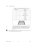
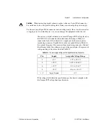
Страница 36: ...1052 are within the allowable limits Referring to Table 2 2 connect one lead of the voltmeter to a supply pin on the remote power monitoring connector 9 pin D Sub on the rear panel Refer to Table 2 1...

Страница 37: ...from the chassis exterior and interior as needed based on the operating environment Periodic cleaning increases reliability Preparation The information in this chapter is designed for use by qualified...

Страница 38: ...ior Cleaning Cautions Avoid getting water inside the chassis during exterior cleaning especially through the top vents Use just enough water to dampen the cloth Do not wash the front or rear panel con...

Страница 39: ...on the chassis You can purchase the same filter media in sheets and make a filter replacement Resetting the AC Mains Circuit Breaker If the PXI 1052 encounters an over current condition the circuit br...

Страница 40: ...ed CompactPCI SCXI or PXI modules Overloading the chassis can cause the breaker to trip Refer to Appendix A Specifications 6 The over current condition that caused the circuit breaker to trip can be d...

Страница 41: ...atures of the chassis may be impaired This appendix contains specifications for the PXI 1052 chassis Electrical AC Input Input voltage range 100 240 VAC Operating voltage range1 90 264 VAC Input frequ...

Страница 42: ...the CompactPCI PXIbackplane You also can use the rear panel 9 pin D Sub connector to control the internal chassis power supply DC Output DC current capacity IMP Maximum ripple and noise 20 MHz bandwi...

Страница 43: ...air circulation positive pressurization using one 115 cfm fan with HIGH AUTO speed selector Intake Bottom rear of chassis Exhaust Along both sides and top of chassis Power supply cooling System Forced...

Страница 44: ...t Notes For EMC compliance you must operate this device with shielded cabling In addition all covers and filler panels must be installed CE Compliance This product meets the essential requirements of...

Страница 45: ...2 Storage Environment Ambient temperature range 20 to 70 C Tested in accordance with IEC 60068 2 1 and IEC 60068 2 2 Storage relative humidity 5 to 95 noncondensing Tested in accordance with IEC 60068...

Страница 46: ...are UL 94 V 0 rated 10 MHz System Reference Clock 10 MHz REF Maximum clock skew between slots 500 ps Built in 10 MHz clock Accuracy 100 ppm guaranteed over the operating temperature range Maximum jitt...

Страница 47: ...kg 22 0 lbs Chassis materials Sheet aluminum EN AW 5754 H22 EN AW 5005 H14 extruded aluminum 6063 T6 cold rolled steel PC ABS Santoprene nylon Finish Conductive clear Iridite on aluminum clear chromat...

Страница 48: ...wn are for the installation of the optional rack mount kits as shown in Figure A 3 The front and rear rack mounting holes size M4 are symmetrical Figure A 1 PXI 1052 Dimensions Front and Side in Inche...

Страница 49: ...Appendix A Specifications National Instruments Corporation A 9 NI PXI 1052 User Manual Figure A 2 PXI 1052 Dimensions Bottom in Inches mm 14 66 372 3 0 95 24 1 1 13 28 6 15 00 381 0...

Страница 50: ...Appendix A Specifications NI PXI 1052 User Manual A 10 ni com Figure A 3 PXI 1052 Rack Mount Kit Components 1 Front Rack Mount Kit 2 PXI 1052 Chassis 3 Rear Rack Mount Kit 1 2 1 3...

Страница 51: ...roller slot Table B 3 shows the P1 J1 connector pinout for the star trigger slot Table B 4 shows the P2 J2 connector pinout for the star trigger slot Table B 5 shows the P1 J1 connector pinout for the...

Страница 52: ...AD 13 GND 18 GND SERR GND 3 3V PAR C BE 1 GND 17 GND 3 3V IPMB_SCL IPMB_SDA GND PERR GND 16 GND DEVSEL GND V I O STOP LOCK GND 15 GND 3 3V FRAME IRDY GND TRDY GND 12 14 Key Area 11 GND AD 18 AD 17 AD...

Страница 53: ...G1 PXI_TRIG0 DEG GND PXI_TRIG7 GND 15 GND PXI_BRSVA15 GND FAL REQ5 GNT5 GND 14 GND AD 35 AD 34 AD 33 GND AD 32 GND 13 GND AD 38 GND V I O AD 37 AD 36 GND 12 GND AD 42 AD 41 AD 40 GND AD 39 GND 11 GND...

Страница 54: ...13 GND 18 GND SERR GND 3 3V PAR C BE 1 GND 17 GND 3 3V IPMB_SCL IPMB_SDA GND PERR GND 16 GND DEVSEL GND V I O STOP LOCK GND 15 GND 3 3V FRAME IRDY BD_SEL TRDY GND 12 14 Key Area 11 GND AD 18 AD 17 AD...

Страница 55: ...I_TRIG0 RSV GND PXI_TRIG7 GND 15 GND PXI_BRSVA15 GND RSV PXI_STAR6 PXI_LBR6 GND 14 GND AD 35 AD 34 AD 33 GND AD 32 GND 13 GND AD 38 GND V I O AD 37 AD 36 GND 12 GND AD 42 AD 41 AD 40 GND AD 39 GND 11...

Страница 56: ...AD 13 GND 18 GND SERR GND 3 3V PAR C BE 1 GND 17 GND 3 3V IPMB_SCL IPMB_SDA GND PERR GND 16 GND DEVSEL GND V I O STOP LOCK GND 15 GND 3 3V FRAME IRDY BD_SEL TRDY GND 12 14 Key Area 11 GND AD 18 AD 17...

Страница 57: ...XI_TRIG0 RSV GND PXI_TRIG7 GND 15 GND PXI_BRSVA15 GND RSV PXI_LBL6 PXI_LBR6 GND 14 GND AD 35 AD 34 AD 33 GND AD 32 GND 13 GND AD 38 GND V I O AD 37 AD 36 GND 12 GND AD 42 AD 41 AD 40 GND AD 39 GND 11...

Страница 58: ...upport Options Contact NI engineers and other measurement and automation professionals by visiting ni com support Our online system helps you define your question and connects you to the experts by ph...

Страница 59: ...need contact your local office or NI corporate headquarters Phone numbers for our worldwide offices are listed at the front of this manual You also can visit the Worldwide Offices section of ni com n...

Страница 60: ...co 10 12 n nano 10 9 micro 10 6 m milli 10 3 k kilo 103 M mega 106 G giga 109 T tera 1012 Symbols Degrees Equal or greater than Equal or less than Percent Ohms A A Amperes AC Alternating current ANSI...

Страница 61: ...requiring a more robust mechanical form factor than desktop PCI It uses industry standard mechanical components and high performance connector technologies to provide an optimized system intended for...

Страница 62: ...g and arbitration for data transfers across the backplane Installing such a device into any other slot can damage the device the PXI backplane or both F FCC Federal Communications Commission filler pa...

Страница 63: ...ominal regular intervals Units seconds RMS K kg Kilograms km Kilometers L lb Pounds LED Light emitting diode line regulation The maximum steady state percentage that a DC voltage output changes as a r...

Страница 64: ...ational Instruments driver which controls the operation of National Instruments data acquisition DAQ devices NI VISA National Instruments implementation of the VISA Virtual Instrument System Architect...

Страница 65: ...ered off but the chassis is still connected to AC power mains star trigger slot This slot is located at Slot 2 and has a dedicated trigger line between each peripheral slot Use this slot for a module...

Страница 66: ...s that can include a name a physical channel input terminal connections the type of measurement or generation and scaling information In Traditional NI DAQ and earlier versions configuring virtual cha...

Страница 67: ...ntions used in the manual vii cooling air cooling of PXI 1052 2 2 air intake figure 2 2 filler panel installation 2 3 setting fan speed 2 3 slot blocker installation 2 3 customer professional services...

Страница 68: ...n speed 2 3 site considerations 2 2 slot blocker installation 2 3 testing power up 2 4 unpacking the PXI 1052 1 1 instrument drivers NI resources C 1 interoperability with CompactPCI 1 6 K key feature...

Страница 69: ...er 2 6 installing in a PXI 1052 chassis figure 2 7 PXI subsystem SCXI control slot 1 7 star trigger and local bus routing figure 1 8 PXI_CLK10 1 8 PXI_CLK10_IN pin 1 8 PXI 1011 chassis See PXI subsyst...

Страница 70: ...ure A 10 safety A 3 star trigger ST slot description 1 6 P1 J1 connector pinouts table B 4 P2 J2 connector pinouts table B 5 star trigger and local bus routing figure 1 8 support technical C 1 system...

Отзывы: