©
National Instruments Corporation
9
NI TB-2630B Installation Instructions
In the 1-wire 128 × 1 topology, the driver establishes a connection from 1wref0 (Bank 0–1, Pin 17) to
com1 (Bank 1, Pin 18).
In the 1-wire dual 64 × 1 topology, the driver establishes the following connections:
•
1wref0 is connected to com1.
•
1wref2 is connected to com5.
In the 1-wire quad 32 × 1 topology, the driver establishes the following connections:
•
1wref0 is connected to com1.
•
1wref1 is connected to com3.
•
1wref2 is connected to com5.
•
1wref3 is connected to com7.
ch110
145
Bank 6, Pin 15
ch111
95
Bank 6, Pin 16
ch112
147
Bank 7, Pin 1
ch113
93
Bank 7, Pin 2
ch114
148
Bank 7, Pin 3
ch115
92
Bank 7, Pin 4
ch116
85
Bank 7, Pin 5
ch117
81
Bank 7, Pin 6
ch118
157
Bank 7, Pin 7
ch119
90
Bank 7, Pin 8
ch120
151
Bank 7, Pin 9
ch121
89
Bank 7, Pin 10
ch122
152
Bank 7, Pin 11
ch123
88
Bank 7, Pin 12
ch124
153
Bank 7, Pin 13
ch125
87
Bank 7, Pin 14
ch126
154
Bank 7, Pin 15
ch127
86
Bank 7, Pin 16
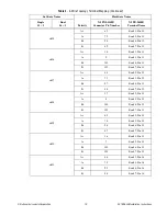
Table 1.
1-Wire and Independent Topology Terminal Mapping (Continued)
Software Name
Hardware Name
Single
128
1
Dual
64
1
Quad
32
1
Octal
16
1
Independent
NI PXI-2530B
Connector Pin Number
NI TB-2630B
Terminal Name


