12
|
ni.com
|
NI PXIe-4463 Calibration Procedure
5.
Stop the task.
6.
Repeat steps 3 to 5 with signal frequencies of 20 Hz, 20 kHz, and 22.4 kHz.
7.
Repeat steps 3 to 6 for pseudodifferential output terminal configuration.
8.
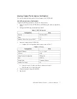
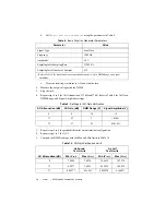
Repeat steps 2 to 7 for AO Attenuation of 17 dB and 37 dB. Refer to Table 9 for AO Gain,
DMM Range, and Signal Amplitude settings.
9.
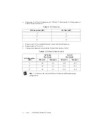
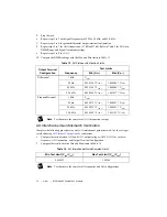
10. Compare the DMM readings with the Max and Min limits in Table 13.
Note
Test limits are the same for all AO Attenuation settings.
AO Interchannel Gain Mismatch Verification
Complete the following procedure to verify AO interchannel gain mismatch. Use the voltages
recorded during
for calculations.
1.
Compute the ratio between AO 0 and AO 1 output voltages (AO 0/AO 1) for each test
frequency, AO Attenuation, and Output Terminal Configuration.
2.
Compare the results with the Min and Max limits in Table 14.
Note
Test limits are the same for all frequencies and AO configurations.
Table 13.
AO Flatness Verification Limits
Output Terminal
Configuration
Frequency
Test Limits
Min (V
rms
)
Max (V
rms
)
Differential
1 kHz
V
1kHz
20 Hz
0.999194 * V
1kHz
1.000806 * V
1kHz
20 kHz
0.999194 * V
1kHz
1.000806 * V
1kHz
22.4 kHz
0.998964 * V
1kHz
1.001037 * V
1kHz
Pseudodifferential
1 kHz
V
1kHz
20 Hz
0.999079 * V
1kHz
1.000921 * V
1kHz
20 kHz
0.999079 * V
1kHz
1.000921 * V
1kHz
22.4 kHz
0.998849 * V
1kHz
1.001152 * V
1kHz
Table 14.
AO Interchannel Gain Mismatch Limits
Min Test Limit (V
rms
/V
rms
)
Max Test Limit (V
rms
/V
rms
)
0.996552
1.00346


