Chapter 2
Installation and Configuration
NI PXI-1031/PXI-1031DC User Manual
2-2
ni.com
•
Part Replacement
—Only service this equipment with parts that are
exact replacements, both electrically and mechanically. Contact
National Instruments for replacement part information. Installation of
parts with those that are not direct replacements may cause harm to
personnel operating the chassis. Furthermore, damage or fire may
occur if replacement parts are unsuitable.
•
Modification
—Do
not
modify any part of the chassis from its original
condition. Unsuitable modifications may result in safety hazards.
Chassis Cooling Considerations
The chassis is designed to operate on a bench or in an instrument rack.
Determine how you want to use the chassis and follow the appropriate
installation instructions.
Providing Adequate Clearance
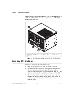
Apertures in the top, bottom, front, rear, and along the right side of the
chassis facilitate power supply and module cooling. Air enters through
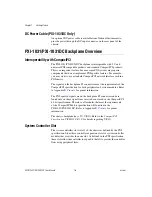
filters and fan inlet in the bottom of the chassis for module cooling. It then
exits through the upper sections at the right side, back, and through the top,
as shown in Figure 2-1. Air cooling the power supply enters the front of the
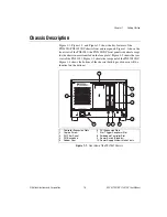
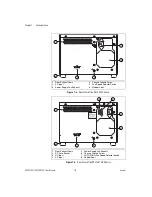
chassis, which is shown in Figure 1-1,
Front View of the PXI-1031 Chassis
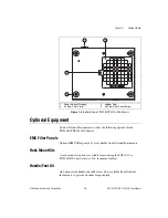
then exits through the rear of the chassis, which is shown in Figure 1-2,
Rear View of the PXI-1031 Chassis
. Place the chassis on a bench top or in an instrument
rack so that the fans (air inlets) and the air outlet apertures along the right
side, the top, and the back of the chassis have adequate ventilation. Provide
at least 44.5 mm (1.75 in.) clearance above, behind, and on the sides of the
unit for adequate venting. High-power applications may require additional
clearance.

