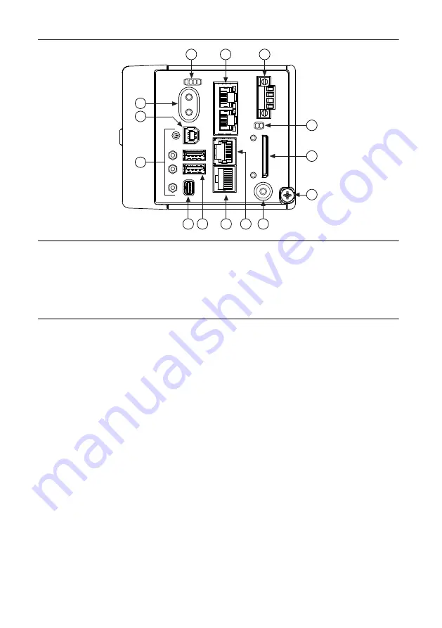
National Instruments NI cRIO-9036 Скачать руководство пользователя страница 7

Figure 2.

 cRIO-9036 Front Panel

1

2

3

4

5

6

8

9

11

14

13

12

10

7

1. LEDs
2. Ethernet Ports
3. Power Connector
4. SD LEDs
5. SD Card Removable Storage
6. Ground Screw
7. USER1 Button

8. RS-232 Serial Port
9. RS-485/422 (DTE) Serial Port
10. USB Host Ports
11. Mini DisplayPort
12. Cable Retention Mounts
13. USB Device Port
14. Power and Reset Buttons

Connecting the cRIO-9036 to Ground

You must connect the cRIO-9036 grounding terminal to the grounding electrode system of the
facility.

What to Use

Ring lug

Wire, 1.3 mm

2

 (16 AWG) or larger

Screwdriver, Phillips #2

What to Do

Complete the following steps to ground the cRIO-9036.
1.

Attach the ring lug to the wire.

2.

Remove the grounding screw from the grounding terminal on the cRIO-9036.

3.

Attach the ring lug to the grounding terminal.

4.

Tighten the grounding screw to 0.5 N · m (4.4 lb · in.) of torque.

5.

Attach the other end of the wire to the grounding electrode system of your facility using a
method that is appropriate for your application.

NI cRIO-9036 Getting Started Guide

  | 

© National Instruments

  | 

7

Содержание NI cRIO-9036

Страница 1: ...w to begin using the National Instruments cRIO 9036 Safety Guidelines Caution Do not operate the cRIO 9036 in a manner not specified in this document Product misuse can result in a hazard You can comp...

Страница 2: ...nclosure rated to at least IP54 as defined by IEC EN 60079 15 Caution Do not insert or remove SD cards unless power has been switched off or the area is known to be nonhazardous Caution The USB host p...

Страница 3: ...ral device or test object or if the product is used in residential or commercial areas To minimize interference with radio and television reception and prevent unacceptable performance degradation ins...

Страница 4: ...ts In addition take precautions when designing selecting and installing measurement probes and cables to ensure that the desired EMC performance is attained Preparing the Environment Ensure that the e...

Страница 5: ...ce Drivers Media 5 Getting Started Guide Installing Software on the Host Computer Before using the cRIO 9036 you must install the following application software and device drivers on the host computer...

Страница 6: ...n the C Series module 3 Align the C Series module with a slot and seat it in the slot until the latches lock in place Removing C Series Modules Verify that power is not connected to the I O connector...

Страница 7: ...rminal to the grounding electrode system of the facility What to Use Ring lug Wire 1 3 mm2 16 AWG or larger Screwdriver Phillips 2 What to Do Complete the following steps to ground the cRIO 9036 1 Att...

Страница 8: ...036 has a primary power input V1 and a secondary power input V2 The POWER LED on the cRIO 9036 indicates which power input is in use as shown in the following table Table 2 POWER LED Indicators LED Co...

Страница 9: ...tive leads of the power supply as shown in the following figure Figure 3 Installing a Ferrite on the Power Leads 2 1 1 Pass the leads through the ferrite twice leaving 50 mm to 75 mm 2 in to 3 in betw...

Страница 10: ...cRIO 9036 When you power on the cRIO 9036 for the first time the device boots into safe mode The POWER LED illuminates the STATUS LED illuminates briefly and then the STATUS LED blinks twice every few...

Страница 11: ...ber such as NI CRIO 9036 1856AAA Setting a System Password Complete the following steps to set a system password Note The default username for the cRIO 9036 is admin There is no default password for t...

Страница 12: ...if you plan on using the cRIO 9036 without the LabVIEW FPGA Module Tip You can use this wizard at anytime to install additional software 7 Click Next 8 Verify that the summary of software to install i...

Страница 13: ...System IP Configuration 1 Put the cRIO 9036 in safe mode and enable the RS 232 serial port by holding the RESET button down for 5 seconds The STATUS LED starts blinking three times every few seconds...

Страница 14: ...d RESET button for 5 s Press and hold RESET button for 5 s Run Mode Safe Mode Press and hold RESET button for 5 s Press and hold RESET button for 5 s Press and hold RESET button for 5 s Press and hold...

Страница 15: ...r longer than five seconds or by enabling safe mode in MAX Refer to the Measurement Automation Explorer MAX Help for information about safe mode Blinks four times and pauses The cRIO 9036 is in safe m...

Страница 16: ...eshooting and application development self help resources to email and phone assistance from NI Application Engineers Visit ni com services for NI Factory Installation Services repairs extended warran...

Страница 17: ...create your service request at ni com support or dial 1 866 ASK MYNI 275 6964 For telephone support outside the United States visit the Worldwide Offices section of ni com niglobal to access the bran...

Страница 18: ...party legal notices in the readme file for your NI product Refer to the Export Compliance Information at ni com legal export compliance for the NI global trade compliance policy and how to obtain rel...

Отзывы: