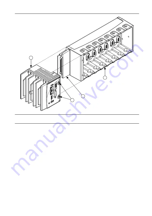
background image

Figure 2.

 Installing the cRIO-9025 on the Chassis

1

4

3

2

1. Controller
2. Captive Screws

3. Chassis Connector
4. Chassis

3.

Slide the cRIO-9025 onto the chassis connector. Press firmly to ensure the chassis
connector and the cRIO-9025 connector are mated.

4.

Using a Phillips #2 screwdriver, tighten the two captive screws on the front of the
cRIO-9025 to 1.3 N · m (11.5 lb · in.) of torque.

Dimensions

The following figure shows the cRIO-9025 dimensions.

4

  | 

ni.com

  | 

NI cRIO-9025 User Manual and Specifications

Содержание NI cRIO-9025

Страница 1: ...LEDs 2 Power Connector 3 RS 232 Serial Port 4 USB Port 5 USB Retention Standoff 6 Reset Button 7 DIP Switches 8 RJ 45 Ethernet Port 1 9 RJ 45 Ethernet Port 2 Refer to the reconfigurable chassis docum...

Страница 2: ...ution For Division 2 and Zone 2 applications install the system in an enclosure rated to at least IP54 as defined by IEC EN 60079 15 Special Conditions for Hazardous Locations Use in Europe and Intern...

Страница 3: ...e product not expressly approved by National Instruments could void your authority to operate it under your local regulatory rules Special Conditions for Marine Applications Some products are Lloyd s...

Страница 4: ...he chassis connector Press firmly to ensure the chassis connector and the cRIO 9025 connector are mated 4 Using a Phillips 2 screwdriver tighten the two captive screws on the front of the cRIO 9025 to...

Страница 5: ...tandard Ethernet connection If neither the host computer nor the controller is connected to a network you can connect the two directly Caution To prevent data loss and maintain the integrity of your E...

Страница 6: ...r for the C Series modules The cRIO 9025 has a primary power input V1 and a secondary power input V2 The cRIO 9025 draws power from the power supply with the higher voltage The cRIO 9025 has one layer...

Страница 7: ...he Power and Status LEDs turn on When the Status LED turns off the POST is complete Related Information LEDs on page 11 Configuring IP Settings and Installing Software on the cRIO 9025 The cRIO 9025 i...

Страница 8: ...ch the LabVIEW Real Time Software Wizard 11 Install LabVIEW Real Time software and device drivers on the controller The cRIO 9025 automatically reboots after the software installation You can now prog...

Страница 9: ...systems LabVIEW maps USB devices to the U V W or X drive starting with the U drive if it is available You can connect multiple USB mass storage devices to the cRIO 9025 if you use a USB hub Refer to...

Страница 10: ...of the CONSOLE OUT switch Table 2 CONSOLE OUT Switch States State Description ON Enables console out You can read the IP address and firmware version of the cRIO 9025 using a serial port terminal prog...

Страница 11: ...application is automatically enabled Note If you want to permanently disable the application from running when the controller powers on you must disable it in LabVIEW For more information about automa...

Страница 12: ...surement Automation Explorer MAX Help for information about configuring devices Blinks twice and pauses An error can occur when an attempt to upgrade the software is interrupted Reinstall software on...

Страница 13: ...he cRIO 9025 to the default network settings 1 Move the IP RESET switch to the ON position 2 Push the RESET button to cycle power to the cRIO 9025 The STATUS LED flashes once indicating that the cRIO...

Страница 14: ...egotiated Ethenert port 2 10 Mbps 100 Mbps auto negotiated Maximum cabling distance 100 m segment RS 232 DTE Serial Port Baud rate 600 bps to 230 400 bps Data bits 5 6 7 8 Stop bits 1 1 5 2 Parity Odd...

Страница 15: ...cRIO 9025 supplying power to eight C Series modules 35 W Voltage requirement On powerup 9 V to 35 V After powerup 6 V to 35 V Note The cRIO 9025 is guaranteed to power up when 9 V is applied to V and...

Страница 16: ...4 2 Maximum altitude 5 000 m Indoor use only Shock and Vibration To meet these specifications for shock and vibration you must panel mount or wall mount the cRIO 9025 system affix ferrules to the ends...

Страница 17: ...rol and laboratory use IEC 61010 1 EN 61010 1 UL 61010 1 CSA 61010 1 EN 60079 0 2012 EN 60079 15 2010 IEC 60079 0 Ed 6 IEC 60079 15 Ed 4 UL 60079 0 Ed 5 UL 60079 15 Ed 3 CSA 60079 0 2011 CSA 60079 15...

Страница 18: ...and directives with which NI complies as well as other environmental information not included in this document Waste Electrical and Electronic Equipment WEEE EU Customers This symbol indicates that wa...

Страница 19: ...your complete resource for technical support At ni com support you have access to everything from troubleshooting and application development self help resources to email and phone assistance from NI...

Страница 20: ...Refer to the NI Trademarks and Logo Guidelines at ni com trademarks for information on NI trademarks Other product and company names mentioned herein are trademarks or trade names of their respective...

Отзывы: