NI 9502 Operating Instructions and Specifications
|
© National Instruments
|
9
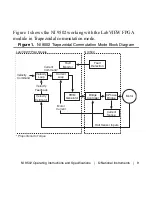
Figure 1 shows the NI 9502 working with the LabVIEW FPGA
module in Trapezoidal commutation mode.
Figure 1.
NI 9502 Trapezoidal Commutation Mode Block Diagram
Velocity
Loop
C
u
rrent
Loop
F
au
lt
Monitor
Bridge
Controller
F
au
lt
Detection
C
u
rrent
S
en
s
e
Motor
Velocity
Comm
a
nd
C
u
rrent
Comm
a
nd*
L
ab
VIEW FPGA Mod
u
le
NI 9502
Motor
C
u
rrent
Velocity
Feed
ba
ck
Velocity
E
s
tim
a
tor
* Proportion
a
l to Torq
u
e
PWM
Gener
a
tor
H
a
ll
S
en
s
or Inp
u
t
s
3
-Ph
as
e
Bridge


