14
|
ni.com
|
NI 9502 Operating Instructions and Specifications
Motor Power Signals
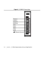
The Phase U, Phase V, and Phase W connections provide PWM
outputs to 3-phase ungrounded Wye or delta connected permanent
magnet brushless motors. Refer to the motor documentation for
motor phase wiring information.
Caution
The motor terminals on this drive are energized
when the module is enabled. Do
not
connect wires to or
disconnect wires from the NI 9502 when it is enabled.
Use a multiconductor cable with an overall shield and conductors
of 12 to 20 AWG for the motor cable. Figure in the
Cable
Requirements for EMC Compliance
section shows a simplified
connection diagram.
Hall Effect Sensor Connections
Use the Hall 1, Hall 2, and Hall 3 inputs to connect the motor Hall
effect sensors. For proper phase switching to occur, the Hall
sensors from the motor must be connected to the correct Hall
inputs on the NI 9502 module. The Hall sensor phase sequence is
motor-dependent, so selecting the correct inputs may require
manually testing the motor wiring. Refer to the
Connecting Hall
Effect Sensors for Trapezoidal Commutation
topic in the
LabVIEW


