


NI 9155 Operating Instructions and Specifications
6
ni.com
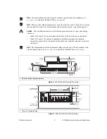
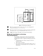
Figure 5.
NI 9155, Side View with Dimensions
Note
For more information about the dimensions of the system, including detailed
dimensional drawings, go to
ni.com/dimensions
.
Note
For more information about mounting the chassis in environments with high shock
and vibration, go to
ni.com/info
and enter the Info Code
criomounting
.
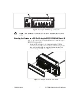
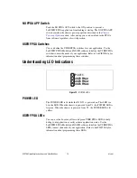
Caution
Make sure that no I/O modules are in the chassis before mounting it.
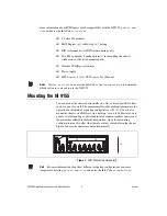
Mounting the Chassis Directly on a Flat Surface
Using the Mounting Holes
For environments with high shock and vibration, National Instruments
requires mounting the chassis directly on a flat, rigid surface using the
mounting holes in the chassis. Complete the following steps to mount the
chassis:
1.
Use the dimensions shown in Figure 4 to prepare the surface for
mounting the chassis.
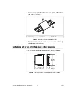
2.
Align the chassis on the surface.
3.
Fasten the chassis to the surface using two M4 or number 8 screws, as
shown in Figure 6. National Instruments does not provide these screws
with the chassis.
44.1 mm
(1.7
3
in.)
25.0 mm
(0.98 in.)
6
3
.1 mm
(2.48 in.)
74.6 mm
(2.94 in.)
50.8 mm
(2.00 in.)