


©
National Instruments
5
NI 9155 Operating Instructions and Specifications
Note
For more information about typical accuracy specifications for modules, go to
ni.com/info
and enter the Info Code
criotypical
.
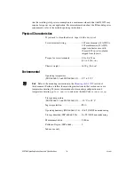
Note
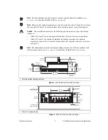
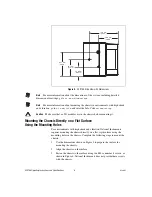
Measure the ambient temperature at each side of the chassis, 63.5 mm (2.5 in.) from
the side and 50.8 mm (2 in.) forward from the rear of the chassis, as shown in Figure 3.
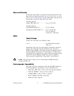
Caution
Your installation must meet the following requirements for space and cabling
clearance:
•
Allow 50.8 mm (2 in.) on the top and the bottom of the chassis for air circulation.
•
Allow 50.8 mm (2 in.) in front of modules for cabling clearance for common
connectors, such as the 10-terminal, detachable screw terminal connector, as shown
in Figure 3.
Note
For information about the minimum cabling clearance for C Series modules with
other connector types, go to
ni.com/info
and enter the Info Code
rdcrioconn
.
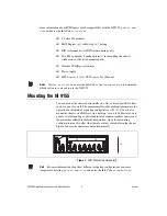
Figure 3.
NI 9155, Bottom View with Dimensions
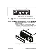
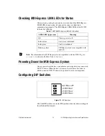
Figure 4.
NI 9155, Front View with Dimensions
1
Measure ambient temperature here.
1
Chassis Grounding Screw
29.1 mm
(1.14 in.)
52.5 mm
(2.07 in.)
50.8 mm
(2.00 in.)
1
6
3
.5 mm
(2.50 in.)
89.4 mm
(
3
.52 in.)
264.
3
mm
(10.41 in.)
50.8 mm
(2.00 in.)
6
3
.5 mm
(2.50 in.)
1
46.0 mm
(1.81 in.)
Cooling O
u
tline
50.8 mm (2.00 in.)
88.1 mm
(
3
.47 in.)
Cooling O
u
tline
50.8 mm (2.00 in.)
51.7 mm
(2.04 in.)
3
6.4 mm
(1.4
3
in.)
19.0 mm
(0.75 in.)
165.1 mm
(6.50 in.)
3
.5 mm
(0.14 in.)
1
NI 9155


