background image

Chapter 3

I/O Information

NI 8350 User Manual

3-8

ni.com

Ethernet

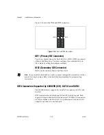
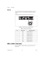
Figure 3-7 shows the location and pinouts for the Ethernet connectors 
on the NI 8350. Table 3-7 lists and describes the Ethernet connector 
signals.

AMP manufactures a mating connector, part number 554739-1.

Figure 3-7.  

Ethernet Connector Location and Pinout

MXI-2 or MXI-4 Connectors

Refer to your MXI-2 or MXI-4 hardware user manual for connector 
information.

Table 3-7.  

Ethernet Connector Signals

Pin

Signal Name

Signal Description

1

D0P

Differential Pair 0+

2

D0N

Differential Pair 0–

3

D1P

Differential Pair 1+

4

D2P

Differential Pair 2+

5

D2N

Differential Pair 2–

6

D1N

Differential Pair 1–

7

D3P

Differential Pair 3+

8

D3N

Differential Pair 3–

Ethernet

1

8

Содержание NI 8350

Страница 1: ...service in house repair center WE BUY USED EQUIPMENT Sell your excess underutilized and idle used equipment We also offer credit for buy backs and trade ins www artisantg com WeBuyEquipment REMOTE IN...

Страница 2: ...PXI VXI NI 8350 User Manual NI 8350 User Manual March 2006 371165B 01...

Страница 3: ...a 82 02 3451 3400 Lebanon 961 0 1 33 28 28 Malaysia 1800 887710 Mexico 01 800 010 0793 Netherlands 31 0 348 433 466 New Zealand 0800 553 322 Norway 47 0 66 90 76 60 Poland 48 22 3390150 Portugal 351 2...

Страница 4: ...ng photocopying recording storing in an information retrieval system or translating in whole or in part without the prior written consent of National Instruments Corporation National Instruments respe...

Страница 5: ...t of Communications DOC Changes or modifications not expressly approved by NI could void the user s authority to operate the equipment under the FCC Rules Class A Federal Communications Commission Thi...

Страница 6: ...7 National Instruments Software 1 8 Chapter 2 Installation and Configuration Safety Information 2 1 Chassis Cooling Considerations 2 2 Providing Adequate Clearance 2 2 Installation 2 2 Connecting Safe...

Страница 7: ...les 2 36 Upgrading and Replacing Hard Disk Drives 2 37 Hard Disk Connectors IDE1 2 2 37 SATA Connectors Supported by 6300ESB ICH SATA1 and SATA2 2 38 Hard Disk Removal 2 40 Hard Disk Installation 2 40...

Страница 8: ...Connector JUSB2 3 13 Chapter 4 Common Configuration Questions General Questions 4 1 Boot Options 4 2 Chassis Configuration 4 2 Basic PXI System Configuration 4 3 Upgrade Information 4 4 Chapter 5 Trou...

Страница 9: ...ncy Interference for information about precautions to take bold Bold text denotes items that you must select or click in the software such as menu items and dialog box options Bold text also denotes p...

Страница 10: ...vision 2 1 PXI Software Specification Revision 2 1 ANSI IEEE Standard 1014 1987 IEEE Standard for a Versatile Backplane Bus VMEbus ANSI IEEE Standard 1155 1998 IEEE VMEbus Extensions for Instrumentati...

Страница 11: ...he metal work Check to make sure all hardware and switches are undamaged If damage appears to have been caused during shipment file a claim with the carrier Retain the packing material for possible in...

Страница 12: ...ntel Pentium 4 3 0 GHz CPU with 800 MHz FSB and 1 MB L2 cache Chipset Intel E7210 chipset Memory 512 MB memory standard 2 256 MB non ECC 32 M 64 bit unbuffered DDR400 3 3 3 DIMM Maximum memory support...

Страница 13: ...n expansion bay SATA or ATA 100 66 33 CD ROM Slim CD ROM drive Onboard LAN Intel 82547 GI Gigabit LAN Intel 82541 GI Gigabit LAN Programmed Ethernet MAC address and EEPROM Onboard I O PS 2 keyboard po...

Страница 14: ...ke up on serial ring Wake up on keyboard mouse from sleep S1 Wake up on USB from sleep S1 Wake up on PCI Supports ACPI S1 S4 S5 functions Devices 6 2 line LCD display panel Up Enter and Next buttons F...

Страница 15: ...CI1 15 JLCD1 16 JACT1 JACT2 17 JFP1 18 J3 J4 J5 19 Intel 6300ESB I O CH 20 JBAT1 J9 21 Battery 22 BIOS 23 JISA1 24 NS PC87366 25 J10 J11 26 J8 27 ATI Rage XL 28 J1 29 Intel 82541GI 30 PCIX1 31 SYSFAN2...

Страница 16: ...atus indicators flash when there is activity on LAN1 or LAN2 Hard disk in use indicator flashes when the system is accessing data on the hard disk The front panel also includes the following LCD contr...

Страница 17: ...8350 is a 1U high rack mountable PC with a remote controller for a PXI or VXI system It is designed for PC control of a PXI or VXI test and measurement system using a minimum of rack space A cable an...

Страница 18: ...These standardized programs match the modular virtual instrument capability of PXI and can reduce your PXI software development time These programs feature extensive libraries of GPIB Serial and VXI i...

Страница 19: ...s CVI delivers a drag and drop editor for building user interfaces a complete ANSI C environment for building your test program logic and a collection of automated code generation tools as well as uti...

Страница 20: ...rom the premise wire safety ground to the NI 8350 chassis ground The earth safety ground must be connected during use of this equipment to minimize shock hazards Refer to the Connecting Safety Ground...

Страница 21: ...lation instructions Providing Adequate Clearance Apertures in the front rear and along both sides of the chassis facilitate power supply and motherboard cooling Air enters through the front and side i...

Страница 22: ...hapter 5 Troubleshooting Connecting Safety Ground The NI 8350 is designed with a three position NEMA 5 15 style plug for the U S that connects the ground line to the chassis ground To minimize shock h...

Страница 23: ...he next option Move to the option on the left Move to the option on the right Enter Select the option Esc Jump to the Exit menu or return to the main menu from a submenu Page Up Increase the numeric v...

Страница 24: ...er values and move from option to option within a submenu To return to the main menu press Esc General Help F1 The BIOS setup program includes a general help screen To access this screen from any menu...

Страница 25: ...this menu to specify your settings for power management Frequency Voltage Control Use this menu to specify your settings for frequency voltage control Load Fail Safe Defaults Use this menu to load th...

Страница 26: ...ing Page Up and Page Down Time hh mm ss Use this menu to set the system time The time format is hour minute second IDE Primary Secondary Master Slave Press Page Up or Page Down to select Manual None o...

Страница 27: ...rror All But Diskette The system stops for any error except a disk error All But Disk Key The system stops for any error except a disk or keyboard error Base Extended Total Memory These read only opti...

Страница 28: ...chnology to increase transaction rates and reduce end user response times The technology treats the two cores inside the processor as two logical processors that can execute instructions simultaneousl...

Страница 29: ...APIC Mode Use this option to enable or disable the Advanced Programmable Interrupt Controller APIC Choose Enable to expand available IRQ resources for the system MPS Version Control for OS Use this o...

Страница 30: ...his option determines whether to keep terminal console redirection running after the OS boots DMI Event Log This option enables the BIOS to log Desktop Management Interface DMI events Clear All DMI Ev...

Страница 31: ...g mechanism is enabled following the appropriate timing delay specified in this option With thermal monitoring enabled clock modulation controlled by the processor internal thermal sensor is also acti...

Страница 32: ...able performance Active to Precharge Delay The option specifies the idle cycles before precharging an idle bank DRAM RAS to CAS Delay This option allows you to set the number of cycles for a timing de...

Страница 33: ...E interface with support for two IDE channels Choose Enabled to activate each channel separately IDE Primary Secondary Master Slave PIO Use these four options to set a Programmed Input Output PIO mode...

Страница 34: ...Compatible Mode with only Serial ATA Enabled and Port 0 set to Secondary Master Enhance Mode Port 0 Tertiary Master Enhanced Mode with Port 0 set to Native Mode Master Enhance Mode Port 1 Quaternary M...

Страница 35: ...port address automatically Onboard Parallel Port This option specifies the I O port address and IRQ of the onboard parallel port Parallel Port Mode This option selects one of the following operating...

Страница 36: ...e specified hardware Resume by Alarm This option enables or disables booting the system on a scheduled time and date Date of Month Alarm This option specifies the date for Resume by Alarm The range is...

Страница 37: ...essage appears Load Optimized Defaults Y N Press Y to load the default factory settings for optimal system performance When you select Load Fail Safe Defaults the following message appears Load Fail S...

Страница 38: ...use of your computer Use Security Option in the Advanced BIOS Features menu to set when the password prompt is required If Security Option is set to System the password is required both at boot and a...

Страница 39: ...Installation and Configuration NI 8350 User Manual 2 20 ni com Jumper Settings Figure 2 1 shows the jumper locations on the NI 8350 Figure 2 1 NI 8350 Jumper Locations 1 J1 2 J8 3 JBAT1 J9 4 J3 J4 J5...

Страница 40: ...ect Connector J9 Figure 2 4 FWH Write Protect Connector J9 Enable Disable VGA Jumper J8 This jumper enables or disables VGA IDSEL Figure 2 5 Enable Disable VGA Jumper J8 2 3 1 2 3 1 PCI X Device Defau...

Страница 41: ...mode the system enters while powered on In Normal Mode the system enters the assigned OS as usual In Configure Mode the system directly enters the BIOS setup utility In this mode you can modify the BI...

Страница 42: ...ls for the peripherals The directory structure under the images directory is logically organized into several levels In the images directory you will find a manuals directory an os directory and direc...

Страница 43: ...Go to the next selection You can use the LCD front panel control buttons to access information under the LCD Info H W Monitor and System Conf menus The menu structures are shown in Figures 2 9 and 2 1...

Страница 44: ...Menu Structure System Conf Host Name Date Time Memory Hard Disk Information LAN1 LAN2 Restart OS Shutdown OS Set Date Set Time Size Usage Available Disk C Size Usage Available Size Usage Available Siz...

Страница 45: ...IOS chsum If the system has BIOS problems it stops at C3 BIOS POST 18 Msg CPU Init If the system has CPU problems it stops at 18 BIOS POST 2B Msg VGA Init If the system has VGA problems it stops at 2B...

Страница 46: ...2002 03 25 Show LCD firmware build date Baud Rate 4 5 9600 Show LCD communication speed with COM port For PC and LCD link Character 5 5 16X2 Show LCD characters Table 2 4 H W Monitor Functions Functi...

Страница 47: ...and allow to set the date Time 3 9 13 24 50 Set Time 1 1 Show the time and allow to set the time Memory 4 9 Size 1 3 Show memory size 511 MB Usage 2 3 Unable to show used memory size 153 MB Available...

Страница 48: ...able 3 3 Unable to show the available size 14 899 MB Disk E 3 4 0 MB Size 1 3 Show partition size 0 MB Usage 2 3 Unable to show the used size 0 MB Available 3 3 Unable to show the available size 0 MB...

Страница 49: ...users to set the system Net Mask 000 000 000 000 LAN2 7 9 100 100 100 101 IP 1 4 Show the system IP information 100 100 100 101 Netmask 2 4 Show the system Net Mask information 255 255 255 0 Set IP Al...

Страница 50: ...Memory The mainboard includes four 184 pin ECC or non ECC nonregistered DDR333 DDR400 SDRAM slots with maximum memory size of 4 GB Install at least one memory module in the slots Figure 2 11 shows the...

Страница 51: ...hifts to the speed of the slower memory Table 2 6 Memory Module Combinations DIMM1 DIMM2 DIMM3 DIMM4 Total Memory 128 MB 1 GB 128 MB 1 GB 128 MB 1 GB 128 MB 1 GB 128 MB 1 GB 128 MB 1 GB 128 MB 1 GB 12...

Страница 52: ...Instruments Corporation 2 33 NI 8350 User Manual Figure 2 12 shows two identical DIMMs in DIMM 1 and DIMM 3 You can also install identical DIMMs in DIMM 2 and DIMM 4 Figure 2 12 Two Identical DIMMs in...

Страница 53: ...m Figure 2 13 shows two different pairs of identical DIMMS two identical DIMMs in DIMM 1 an DIMM 3 and two identical DIMMs in DIMM 2 and DIMM 4 Figure 2 13 Two Different Pairs of Identical DIMMs 1 Fir...

Страница 54: ...2 14 shows four identical DIMMs installed in DIMM 1 through DIMM 4 Figure 2 14 Four Identical DIMMs Installing DDR Modules Complete the following steps to install DDR modules 1 Press the cover release...

Страница 55: ...serted as shown in the following figure 4 When the module is fully inserted the plastic clip at each side of the slot automatically closes as shown in the following figure 5 Replace the NI 8350 cover...

Страница 56: ...8350 IDE and SATA connector locations Figure 2 15 NI 8350 IDE and SATA Connectors Hard Disk Connectors IDE1 2 The mainboard has a 32 bit Enhanced PCI IDE and Ultra DMA 33 66 100 controller that provid...

Страница 57: ...connect a Master and Slave drive Note If you install two hard disks on a cable you must configure the second drive to Slave mode by setting its jumper Refer to the hard disk documentation for jumper...

Страница 58: ...able 2 7 lists and describes the SATA1 and SATA2 connector signals Figure 2 17 SATA1 and SATA2 Connector Figure 2 18 shows an optional serial ATA cable Figure 2 18 Serial ATA Cable Table 2 7 SATA Conn...

Страница 59: ...e be sure the NI 8350 is powered off and not connected to AC power Complete the following steps to install a hard disk drive 1 Press the cover release buttons on the top of the NI 8350 2 Push the cove...

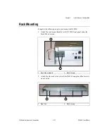
Страница 60: ...ounting Complete the following steps to rack mount the NI 8350 1 Attach the rack mount handles to the NI 8350 front panel using the black M4x6 screws 2 Attach the side rails to the sides of the NI 835...

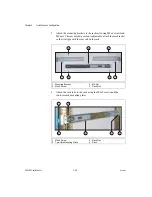
Страница 61: ...ts The rear bracket position is adjustable attach the rear bracket so that it aligns with the rear rail on the rack 4 Attach the rack rails to the rack using the M5x8 screws and the two hole rack moun...

Страница 62: ...NI 8350 halfway into the rack 6 Press the locking tabs on both sides of the NI 8350 and slide the NI 8350 fully into the rack Note The locking tabs lock the NI 8350 halfway into the rack so that it c...

Страница 63: ...includes a preinstalled OS In some cases you may want to reinstall the OS or install a different OS from the integrated CD ROM drive To install from the CD ROM drive you must change the boot device r...

Страница 64: ...ternal Connector Description Keyboard PS 2 5 pin Din PS 2 style keyboard Mouse PS 2 5 pin Din PS 2 style mouse USB USB 4 pin Series A stacked receptacle USB 2 0 capable USB USB 4 pin Series A stacked...

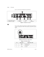
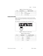
Страница 65: ...oard and mouse connectors on the NI 8350 Table 3 2 lists and describes the PS 2 connector signals Figure 3 2 PS 2 Connector Location and Pinout 1 PS 2 Keyboard Connector 2 PS 2 Mouse Connector 3 USB P...

Страница 66: ...ists and describes the USB connector signals AMP manufactures a USB mating connector part number 787633 Figure 3 3 USB Connector Location and Pinout 4 VCC VCC 5 CLK Clock Keyboard 6 NC Clock Mouse Tab...

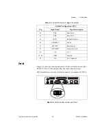
Страница 67: ...1284 connector signals Figure 3 4 Parallel Port Connector Location and Pinout Table 3 4 Parallel Port Connector Signals Pin Default Configuration LPT Signal Name Signal Description 1 BUSY Device Busy...

Страница 68: ...gnal AMP manufactures a serial port mating connector part number 745491 5 Figure 3 5 Serial Connector Location and Pinout 12 PD6 Data Bit 6 13 PD7 Data Bit 7 14 INIT Initialize Printer 15 STROBE Strob...

Страница 69: ...ctures a mating connector with part numbers 748364 1 housing and 748333 2 pin contact Figure 3 6 VGA Connector Location and Pinout Table 3 5 Serial Connector Signals Pin Signal Name Signal Description...

Страница 70: ...3 6 VGA Connector Signals Pin Signal Name Signal Description 1 R Red 2 G Green 3 B Blue 4 NC Not Connected 5 GND Ground 6 GND Ground 7 GND Ground 8 GND Ground 9 5V 5 V 10 GND Ground 11 NC Not Connect...

Страница 71: ...er 554739 1 Figure 3 7 Ethernet Connector Location and Pinout MXI 2 or MXI 4 Connectors Refer to your MXI 2 or MXI 4 hardware user manual for connector information Table 3 7 Ethernet Connector Signals...

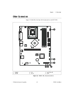
Страница 72: ...truments Corporation 3 9 NI 8350 User Manual Other Connectors Figure 3 8 shows the locations of other connectors on the NI 8350 Figure 3 8 NI 8350 Other Connector Locations 1 JIPMB1 2 JUSB2 3 JCI1 4 J...

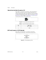
Страница 73: ...e BIOS utility and clear the record Refer to the Advanced BIOS Features section of Chapter 2 Installation and Configuration for information about the Case Open Warning feature Figure 3 9 Chassis Intru...

Страница 74: ...ncludes one I2C also known as I2C bus connector to connect to the System Management Bus SMBus interface Figure 3 11 I2C Bus Connector JIPMB1 Table 3 9 LCD Panel Connector Signals Pin Signal Name 1 SOU...

Страница 75: ...s for LAN2 jack Both LAN1 and LAN2 jacks are on the rear panel Figure 3 12 LAN LED Connectors JACT1 and JACT2 Front Panel Connector JFP1 The mainboard includes one front panel connector for electrical...

Страница 76: ...speed USB interface peripherals such as USB HDD digital cameras MP3 players printers modems and so on Figure 3 14 Front USB Connector JUSB2 Table 3 11 Front Panel Connector Signals Pin Signal Name Si...

Страница 77: ...Chapter 3 I O Information NI 8350 User Manual 3 14 ni com Table 3 12 Front USB Connector Signals Pin Signal Name Pin Signal Name 1 VCC 6 USB1 2 VCC 7 GND 3 USB0 8 GND 4 USB1 9 Key 5 USB0 10 NC...

Страница 78: ...ty on LAN1 and LAN2 The hard drive LED lights when there is hard drive activity on the NI 8350 For more information refer to Figure 1 2 Front View of the NI 8350 How do I check the configuration of th...

Страница 79: ...ll work in a DOS environment How do I configure the controller to boot from these devices Press Delete enter the BIOS and select Advanced BIOS Features You can set the boot order using and Set the ord...

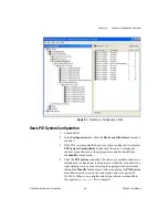
Страница 80: ...t click this entry to display the shortcut menu then select the appropriate controller model from the Identify As submenu 4 Click the PXI System controller The chassis or multiple chassis in a multich...

Страница 81: ...from the chassis ini file Device drivers and other utility software read the pxisys ini file to obtain system information For detailed information about initialization files refer to the PXI specific...

Страница 82: ...tor work with a different PC If it hangs note the last screen output that you saw for reference when consulting National Instruments technical support What has changed about the system Did you recentl...

Страница 83: ...Try the module in a different chassis or with a different controller Also remove any external cables or terminal blocks connected to the system If the module does not work in these cases it is likely...

Страница 84: ...y 50 60 Hz Operating frequency range1 47 63 Hz Input current rating 6 3 A Power disconnect The AC power cable provides main power disconnect Depressing the front panel power switch enables or inhibits...

Страница 85: ...100 support USB ports Four USB 2 0 ports Keyboard PS 2 keyboard port Mouse PS 2 mouse port Video VGA port onboard ATI Rage XLwith with 8 MB SDRAM Serial One RS 232 serial port Parallel One parallel po...

Страница 86: ...64 bit DDR400 SDRAM 3 3 3 non ECC unbuffered 184 pin DIMMs 4 GB memory upgrade 4 1 GB 128 M 64 bit DDR400 SDRAM 3 3 3 non ECC unbuffered 184 pin DIMMs Mechanical Overall dimensions standard chassis H...

Страница 87: ...ectromagnetic Compatibility Emissions EN 55011 Class A at 10 m FCC Part 15A above 1 GHz Immunity EN 61326 1997 A2 2001 Table 1 CE C Tick and FCC Part 15 Class A Compliant Note For EMC compliance opera...

Страница 88: ...every question receives an answer For information about other technical support options in your area visit ni com services or contact your local office at ni com contact Training and Certification Vis...

Страница 89: ...T tera 1012 Symbols Degrees Ohms Percent A A Amperes A D Analog to digital Most often used as A D converter AC Alternating Current ACPI Advanced Configuration and Power Management Interface ANSI Amer...

Страница 90: ...are the fundamental level of any PC or compatible computer BIOS functions embody the basic operations needed for successful use of the computer s hardware resources C C Celsius CAS Column Address Str...

Страница 91: ...face DRAM Dynamic RAM Random Access Memory storage that the computer must refresh at frequent intervals E ECC Error Correcting Code EEPROM Electronically Erasable Programmable Read Only Memory EMC Ele...

Страница 92: ...specifically the 16 bit AT bus K KB Kilobytes of memory L LAN Local Area Network communications network that serves users within a confined geographical area It is made up of servers workstations a n...

Страница 93: ...F Platform Event Filter PIO Programmed Input Output POSC Power On Self Configuration POST Power On Self Test PXI PCI eXtensions for Instrumentation an open implementation of CompactPCI that adds elect...

Страница 94: ...ersion of SDRAM technology SO DIMM Small Outline Dual In line Memory Module SPD Serial Presence Detect EEPROM SRAM Static RAM a memory chip that requires power to hold its content It does not require...

Страница 95: ...13 control keys 2 4 entering 2 3 Frequency Voltage Control menu 2 17 getting help 2 5 general help 2 5 Main menu 2 5 submenus 2 5 Integrated Peripherals menu 2 14 IPMI V1 5 BIOS Features menu 2 8 loa...

Страница 96: ...onal Instruments note 1 7 installing 2 35 removing 2 36 debug functions before boot to OS table 2 26 Delay Prior to Thermal menu option 2 12 diagnostic tools NI resources B 1 DIMM location figure 2 31...

Страница 97: ...ing Technology menu option 2 9 I I2C bus connector JIPMB1 3 11 pinout figure 3 11 signals table 3 11 IDE connector location figure 2 37 IDE controller using SCSI hard drive in addition 4 1 IDE DMA Tra...

Страница 98: ...faults menu 2 6 loading fail safe 2 18 loading optimized defaults 2 18 M Main BIOS menu 2 5 mainboard specifications A 1 maintenance of PXI 1031 cleaning exterior cleaning 2 44 manuals directory 2 23...

Страница 99: ...ipment 1 7 overview 1 7 peripheral expansion overview table 3 1 power source connecting to 2 3 rack mounting 1 7 2 41 safety and caution notices 2 1 safety ground connecting 2 3 SATA connector locatio...

Страница 100: ...37 Resume by Alarm menu option 2 17 S safety and caution notices 2 1 safety ground connecting 2 3 safety specifications A 4 SATA connector locations figure 2 37 SATA connector signals figure 2 39 SATA...

Страница 101: ...splay 5 2 troubleshooting NI resources B 1 two different pairs of identical DIMMs figure 2 34 two identical DIMMs in DIMM 1 and DIMM 3 figure 2 33 U Universal Serial Bus USB 3 1 connector location and...

Страница 102: ...service in house repair center WE BUY USED EQUIPMENT Sell your excess underutilized and idle used equipment We also offer credit for buy backs and trade ins www artisantg com WeBuyEquipment REMOTE IN...

Отзывы: