background image

NI 6509 User Guide and Specifications

20

ni.com

Power-on state ........................................Inputs high-Z (default), 

user-selectable input, 
output 1 or 0

Data transfers ..........................................Interrupts, programmed I/O

I/O connector ..........................................100-pin female 0.050 series SCSI

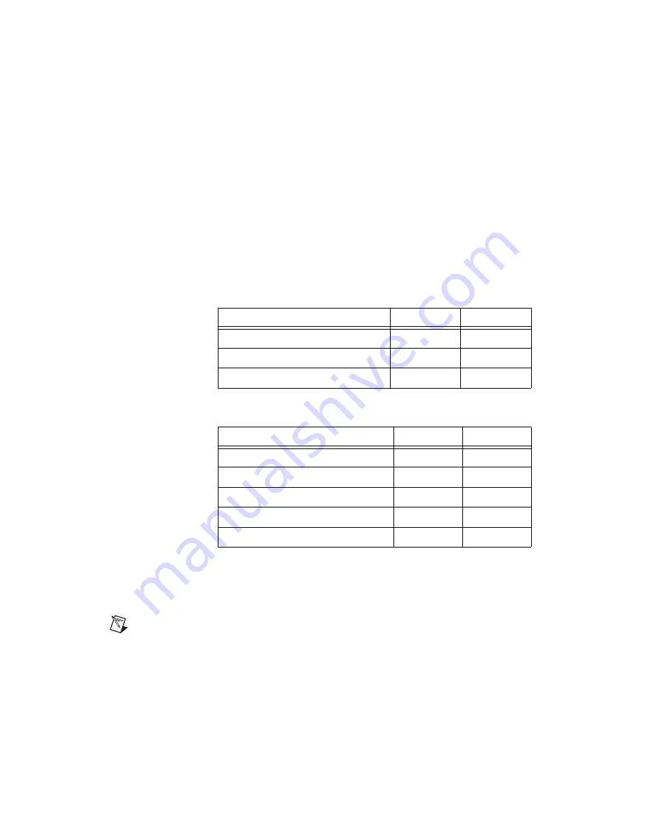
Digital Logic Levels

Input Signals

The maximum input logic high and output logic high voltages assume a 
Vcc supply voltage of 5.0 V. Given a Vcc supply voltage of 5.0 V, the 
absolute maximum voltage rating for each I/O line is –0.5 V to 5.5 V with 
respect to GND.

Output Signals (Vcc = 5 V)

The total current sinking/sourcing from one port cannot exceed 100 mA.

+5V power available at
I/O connector (pins 49 and 99) ...............+4.65 to +5.25 V

Note

The I/O connector power has a fuse for overcurrent protection. This fuse is not 

customer replaceable. If the fuse is blown, return the device to NI for repair.

Programmable power-up states
response time ..........................................400 ms

Level

Min

Max

Input voltage (V

I

)

0 V

Vcc

Input logic low voltage (V

IL

)

0.8 V

Input logic high voltage (V

IH

)

2 V

Level

Min

Max

High-level output current (I

OH

)

–24 mA

Low-level output current (I

OL

)

24 mA

Output voltage (V

O

)

0

Vcc

Output low voltage (V

OL

), at 24 mA

0.55 V

Output high voltage (V

OH

), at –24 mA

3.7 V

Содержание NI 6509

Страница 1: ...are 3 Functional Overview 4 Safety Information 4 Related Documentation 6 Features 7 Digital Filtering 7 Digital Filtering Example 8 Programmable Power Up States 8 Change Detection 9 Change Detection E...

Страница 2: ...09 device and the software are installed the DAQ device appears under the Devices and Interfaces branch of the MAX configuration tree If the DAQ device does not appear in MAX use the following trouble...

Страница 3: ...modify example code and save it in an application You can use examples to develop a new application or add example code to an existing application To locate LabVIEW and LabWindows CVI examples open th...

Страница 4: ...dify the DIO device except as described in this help file Use the DIO device only with the chassis modules accessories and cables specified in the installation instructions You must have all covers an...

Страница 5: ...ody and the connector block signal when hot swapping modules Remove power from signal lines before connecting them to or disconnecting them from the DIO device Operate the DIO device at or below the m...

Страница 6: ...is for measurements performed at the primary electrical supply installation 1 000 V Examples include electricity meters and measurements on primary overcurrent protection devices and on ripple contro...

Страница 7: ...eed to be passed and blocked You can enable filtering on as many input lines as necessary for your application All filtered lines share the same timing interval which ranges from 400 ns to 200 ms Inte...

Страница 8: ...nsition The same filtering applies to falling 1 to 0 transitions Programmable Power Up States At power up the output drives on the NI 6509 are disabled All lines are user configurable for high impedan...

Страница 9: ...the changes occurs but it does not report which line changed or if the line was rising or falling After a change you can read the input lines to determine the current line states The maximum rate of c...

Страница 10: ...Timer The watchdog timer is a software configurable feature used to set critical outputs to safe states in the event of a software failure a system crash or any other loss of communication between the...

Страница 11: ...digital I O cable with the SCB 100 connector block or use the R1005050 ribbon cable with the CB 50 or CB 50LP connector block Caution Do not make connections to the digital I O that exceed the maximu...

Страница 12: ...4 P2 4 P5 5 P2 5 P5 6 P2 6 P5 7 5 V P9 0 P6 0 P9 1 P6 1 P9 2 P6 2 P9 3 P6 3 P9 4 P6 4 P9 5 P6 5 P9 6 P6 6 P9 7 P6 7 P10 0 P7 0 P10 1 P7 1 P10 2 P7 2 P10 3 P7 3 P10 4 P7 4 P10 5 P7 5 P10 6 P7 6 P10 7 P...

Страница 13: ...P2 4 P2 5 P2 6 P2 7 GND P3 1 P3 2 P3 4 P3 5 P3 6 P3 7 P3 0 P3 3 P4 0 P4 1 P4 2 P4 3 P4 4 P4 5 P4 6 P4 7 P5 0 P5 1 P5 2 P5 3 P5 4 P5 5 P5 6 P5 7 49 50 47 48 45 46 43 44 41 42 39 40 37 38 35 36 33 34 31...

Страница 14: ...35 37 39 41 43 45 47 P0 7 0 Bi directional data lines for port 0 P0 7 P0 0 34 36 38 40 42 44 46 48 P3 7 0 Bi directional data lines for port 3 P3 7 P3 0 49 99 5 V supply 5 volts provides 5 V power sou...

Страница 15: ...Signal Connections The maximum input logic high and output logic high voltages assume a Vcc supply voltage of 5 V The absolute maximum voltage rating is 0 5 to 5 5 V with respect to GND Refer to the...

Страница 16: ...in the inductive load These flyback voltages can damage the outputs and or the power supply To limit these flyback voltages at the inductive load install a flyback diode across the inductive load For...

Страница 17: ...ay less than 24 mA driving a relay greater than 24 mA and driving solid state relays Driving a Relay 24 mA Figures 7 and 8 show examples of connecting the NI 6509 to a relay that does not require more...

Страница 18: ...urrent These examples use an additional transistor circuit Figure 9 NI 6509 Sinking Connection Example 24 mA Figure 10 NI 6509 Sourcing Connection Example 24 mA Driving SSRs Figure 11 shows an example...

Страница 19: ...load current 250 mA on 5 VDC With a load use the following equation to determine the power consumption on a 5 V rail In the equation j is the number of channels you are using to source current Power...

Страница 20: ...ND Output Signals Vcc 5 V The total current sinking sourcing from one port cannot exceed 100 mA 5V power available at I O connector pins 49 and 99 4 65 to 5 25 V Note The I O connector power has a fus...

Страница 21: ...evice is intended for indoor use only Operating Environment Ambient temperature range 0 to 55 C tested in accordance with IEC 60068 2 1 and IEC 60068 2 2 Relative humidity range 10 to 90 noncondensing...

Страница 22: ...Safety This product is designed to meet the requirements of the following standards of safety for electrical equipment for measurement control and laboratory use IEC 61010 1 EN 61010 1 UL 61010 1 CSA...

Страница 23: ...this product visit ni com certification search by model number or product line and click the appropriate link in the Certification column Environmental Management National Instruments is committed to...

Отзывы: