


8
|
ni.com
|
NI CVS-1459RT Getting Started Guide
Wiring Power to the NI CVS-1459RT
Refer to Figure 1 while connecting the NI CVS-1459RT power supplies.
Connecting the System Power Supply
Complete the following steps to supply power to the NI CVS-1459RT.
1.
Make sure the power source is turned off.
2.
If the power connector plug is connected to the chassis, disconnect it from the device.
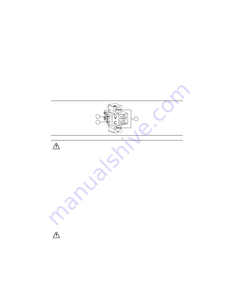
Figure 3 shows the terminal screws, which secure the wires in the screw terminals, and the
connector screws, which secure the connector plug on the chassis.
Figure 3.
Power Screw Terminal Connector Plug
Caution
Do
not
tighten or loosen the terminal screws on the power connector while
the power is on.
3.
Connect the positive lead of the power source to the V terminal of the power connector plug
and tighten the terminal screw to 0.2 to 0.25 N · m (1.8 to 2.2 lb · in.) of torque.
4.
Connect the negative lead of the power source to the C terminal of the power connector plug
and tighten the terminal screw to 0.2 to 0.25 N · m (1.8 to 2.2 lb · in.) of torque.
5.
Install the power connector plug into the SYSTEM power receptacle on the
NI CVS-1459RT chassis and tighten the connector screws to 0.4 N · m (3.5 lb · in.) of
torque.
6.
Turn on the external power source. Verify the PWR/FAULT LED is lit green.
Connecting the Isolated Outputs Power Supply
Complete the following steps to supply power to the isolated outputs.
1.
Make sure the power source is turned off.
2.
If the power connector plug is connected to the chassis, disconnect it from the device.
Figure 3 shows the terminal screws, which secure the wires in the screw terminals, and the
connector screws, which secure the connector plug on the chassis.
Caution
Do
not
tighten or loosen the terminal screws on the power connector while
the power is on.
1
V (Positive) Terminal Screw
2
C (Negative) Terminal Screw
3
Connector Screws
1
2
3


