Pfaff 335, Instruction Manual
The Dremel 335 Operating/Safety Instructions Manual is a crucial companion for any Dremel 335 owners, providing essential guidelines to maximize user safety and product operation. This comprehensive manual is available for download free of charge from our website, ensuring easy access and empowering users to operate the product with confidence.
Share
Download


Reviews:
No comments
Related manuals for 335

2 Line KX-TG9541C
Brand: Panasonic Pages: 20
Pulsar E 300
Brand: Fellowes Pages: 7
Helios 30
Brand: Fellowes Pages: 8
Helios 60
Brand: Fellowes Pages: 8

FOTOMOUNT F32
Brand: Fastbind Pages: 21

3622S
Brand: Janome Pages: 72

3734-2/01
Brand: Pfaff Pages: 80
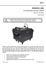
STRATUS-1200
Brand: Qtx Pages: 5

OFX 550
Brand: Olivetti Pages: 83

Highlight MERCHANDISER 1RHCC30
Brand: Zero Zone Pages: 53

FI-BP-15N
Brand: Foamit Pages: 10

Phonefax 35DS
Brand: Sagem Pages: 48

SFAX-500
Brand: Samyung Pages: 87

K4-D Series
Brand: Jack Pages: 37

HCH Series
Brand: Happy Pages: 2

FOGSPRAY 3000 RGB
Brand: Mac Mah Pages: 31

KING COBRA 1200 PRO
Brand: U.S. Products Pages: 12

08001B
Brand: Clarke Pages: 65


