National Instruments cRIO-9068 Скачать руководство пользователя страница 5

Table 3. Power Accessories

Accessory

Part Number


NI PS-15 Power Supply, 24 VDC, 5 A, 100-120/200-240 VAC Input

781093-01

NI PS-10 Desktop Power Supply, 24 VDC, 5 A, 100-120/200-240 VAC Input 782698-01

4-Position Gold Power Supply Plugs (Quantity 5)

783529-01

NI 9979 Strain Relief for 4-Position Power Connector

196939-01

Related Information

POWER LED Indicators

 on page 10

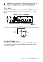
RJ-45 Gigabit Ethernet Ports

The cRIO-9068 has two tri-speed RJ-45 Gigabit Ethernet ports. By default, both Ethernet ports
are enabled and configured to obtain an IP address automatically. The Ethernet ports can be
configured in MAX.

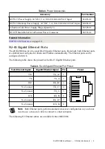
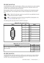
The following table shows the pinout for the RJ-45 Gigabit Ethernet ports.

Table 4. RJ-45 Gigabit Ethernet Port Pinout

Fast Ethernet Signal

Gigabit Ethernet Signal

Pin

Pinout


TX+

TX_A+

1

1
2
3
4
5
6
7
8

TX-

TX_A-

2

RX+

RX_B+

3

No Connect

TX_C+

4

No Connect

TX_C-

5

RX-

RX_B-

6

No Connect

RX_D+

7

No Connect

RX_D-

8

Note


Both Ethernet ports perform automatic crossover configuration so you do not

need to use a crossover cable to connect to a host computer.

The following NI Ethernet cables are available for the cRIO-9068.

NI cRIO-9068 User Manual

  | 

© National Instruments

  | 

5

Содержание cRIO-9068

Страница 1: ...h GigE MAC PHY GigE MAC PHY Xilinx Zynq 7020 XC7Z020 All Programmable SoC RGMII RGMII ONFI NI cRIO 9068 Hardware Data C Series Module C Series Module USB 2 0 Host Port RS 232 Serial Port RS 232 Serial...

Страница 2: ...RIO 9068 with this setting on starts the cRIO 9068 without launching LabVIEW Real Time or any startup applications In safe mode the cRIO 9068 launches only the services necessary for updating configur...

Страница 3: ...once loaded Enable Secure Shell SSH Logins Rebooting the cRIO 9068 with this setting on starts sshd on the cRIO 9068 Starting sshd enables logins over SSH an encrypted communication protocol Note Vis...

Страница 4: ...ng table shows the pinout for the power connector Table 2 Power Connector Pinout Pinout Pin Description V1 C V2 C V1 Primary power input C Common V2 Secondary power input C Common If you apply power t...

Страница 5: ...rnet ports are enabled and configured to obtain an IP address automatically The Ethernet ports can be configured in MAX The following table shows the pinout for the RJ 45 Gigabit Ethernet ports Table...

Страница 6: ...a hazardous location or connected to high voltages If the cRIO 9068 is not in a hazardous location you can connect and disconnect USB devices without affecting operation The following table shows the...

Страница 7: ...n on serial port behavior during FPGA reconfiguration visit ni com info and enter Info Code crioserial The following table shows the pinout for an RS 232 serial port Table 8 RS 232 Serial Port Pinout...

Страница 8: ...i com info and enter Info Code crioserial The following table shows the pinout for the RS 485 serial port Table 10 RS 485 Serial Port Pinout Pinout Pin Signal 1 2 3 4 5 6 7 8 9 1 Ground 2 No Connect 3...

Страница 9: ...to default settings 1 Hold the RESET button for 5 seconds and then release it to boot the controller in safe mode and enable Console Out 2 Hold the RESET button again for 5 seconds to boot the contro...

Страница 10: ...ET button for 5 s Console Out enabled Network settings reset RT Startup App disabled FPGA Startup App disabled Console Out enabled RT Startup App disabled FPGA Startup App disabled Safe Mode LEDs The...

Страница 11: ...The cRIO 9068 is in user directed safe mode or the cRIO 9068 is in install mode to indicate that software is currently being installed This pattern may also indicate that the user has forced the cRIO...

Страница 12: ...FPGA1 LED Use the USER FPGA1 LED to help debug your application or retrieve application status Refer to the LabVIEW Help for information about programming this LED Yellow Ethernet LED Indicators The...

Страница 13: ...k at startup You can set the real time clock using MAX or you can set the clock programmatically using LabVIEW Refer to the specifications on ni com manuals for the real time clock accuracy specificat...

Страница 14: ...IO 9068 if the application requires this For more information visit ni com info and enter the Info Code RT_Paths Mounting the Device To obtain the maximum allowable ambient temperature of 70 C you mus...

Страница 15: ...ings and 3D models visit ni com dimensions and search for the module number Figure 7 cRIO 9068 Front Dimensions 302 8 mm 11 92 in 88 1 mm 3 47 in 4 0 mm 0 16 in Figure 8 cRIO 9068 Side Dimensions 44 1...

Страница 16: ...for C Series modules visit ni com info and enter the Info Code crioconn Figure 10 cRIO 9068 Cabling Clearance Cabling Clearance 29 1 mm 1 14 in Ambient Temperature Measure the ambient temperature at e...

Страница 17: ...gh the cRIO 9068 What to Do Complete the following steps to mount the cRIO 9068 directly on a flat surface 1 Prepare the surface for mounting the cRIO 9068 using the Surface Mounting Dimensions 2 Alig...

Страница 18: ...an use the NI panel mounting kit to mount the cRIO 9068 on a panel What to Use cRIO 9068 Screwdriver Phillips 2 NI panel mounting kit 782863 01 Panel mounting plate M5 or number 10 screw x4 What to Do...

Страница 19: ...ximum screw size is M5 or number 10 Panel Mounting Dimensions The following figure shows the panel mounting dimensions for the cRIO 9068 Figure 13 cRIO 9068 Panel Mounting Dimensions 355 6 mm 14 00 in...

Страница 20: ...he NI DIN rail mounting kit because they are the correct depth and thread for the DIN rail clip Clipping the Device on a DIN Rail Complete the following steps to clip the cRIO 9068 on a DIN rail 1 2 1...

Страница 21: ...g kit Mounting the Device on a Desktop You can use the NI desktop mounting kit to mount the cRIO 9068 on a desktop What to Use cRIO 9068 Screwdriver Phillips 1 Screwdriver Phillips 2 NI desktop mounti...

Страница 22: ...from the back of the chassis on the front panel side 2 Use the screwdriver and the two M3x20 screws to attach the adapter bracket to the chassis 3 Align one of the end brackets with the mounting hole...

Страница 23: ...127 0 mm 5 00 in 130 0 mm 5 12 in Worldwide Support and Services The NI website is your complete resource for technical support At ni com support you have access to everything from troubleshooting and...

Страница 24: ...I Trademarks and Logo Guidelines at ni com trademarks for information on NI trademarks Other product and company names mentioned herein are trademarks or trade names of their respective companies For...

Отзывы: