
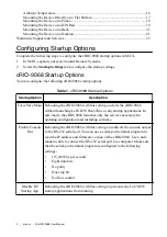

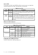


User LEDs
You can define the USER1 and USER FPGA1 LEDs to meet the needs of your application.
The following table lists the USER1 and USER FPGA1 LED indicators.
Table 14. User LEDs
LED
LED Color
Description
USER1
Green
Use LabVIEW Real-Time to define the USER1 LED with the RT
LEDs VI. For more information about the RT LEDs VI, refer to
the
LabVIEW Help
.
Yellow
USER
FPGA1
Green
Use the LabVIEW FPGA Module and NI-RIO Device Drivers
software to define the USER FPGA1 LED. Use the USER FPGA1
LED to help debug your application or retrieve application status.
Refer to the
LabVIEW Help
for information about programming
this LED.
Yellow
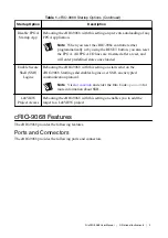
Ethernet LED Indicators
The following table lists the Ethernet LED indicators.
Table 15. Ethernet LED Indicators
LED
LED Color
LED Pattern
Indication
ACT/LINK
—
Off
LAN link not established
Green
Solid
LAN link established
Flashing
Activity on LAN
10/100/1000
Yellow
Solid
1,000 Mbit/s data rate selected
Green
Solid
100 Mbit/s data rate selected
—
Off
10 Mbit/s data rate selected
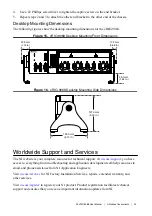
Chassis Grounding Screw
The cRIO-9068 provides a chassis grounding screw.
12
|
ni.com
|
NI cRIO-9068 User Manual