background image

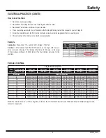
How to Use This Table

1.  Determine your supply voltage.
2.  Determine the total length of your cord including all extension cords.
3.  Determine the maximum amp draw for your machine.
4. 

Trace your voltage across the top of the table to the first length that is greater than or equal to your cord length.

5. 

Follow the column down to the first row that contains a maximum amp draw greater than or equal to yours.

6.  This cell contains the minimum wire size for your application.

Example

Application:

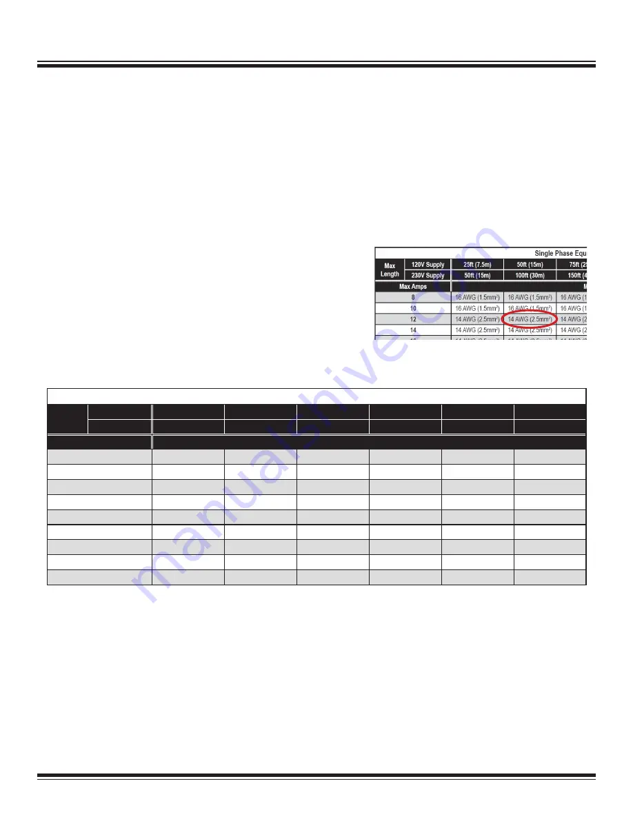
  Max Amps = 11A, Length = 40ft, Voltage = 120V 1ph

Solution:

  40ft is between the 25ft and 50ft columns, so the larger of the two col-

umns is chosen. Likewise, 11A is between the 10A and 12A rows, so the larger 

of the two rows is chosen. 14 AWG (2.5mm

2

) is the minimum wire size for this 

example.

Extension Cord Sizes

Safety

9

ELECTRICAL PRACTICES (CONT’D)

Single Phase Equipment

Max

Length

120V Supply

25ft (7.5m)

50ft (15m)

75ft (25m)

100ft (30m)

150ft (45m)

200ft (60m)

230V Supply

50ft (15m)

100ft (30m)

150ft (45m)

200ft (60m)

300ft (90m)

400ft (120m)

Max Amps

Minimum Wire Size

8

16 AWG (1.5mm

2

) 16 AWG (1.5mm

2

) 16 AWG (1.5mm

2

) 16 AWG (1.5mm

2

) 14 AWG (2.5mm

2

) 14 AWG (2.5mm

2

)

10

16 AWG (1.5mm

2

) 16 AWG (1.5mm

2

) 16 AWG (1.5mm

2

) 16 AWG (1.5mm

2

) 14 AWG (2.5mm

2

)

12 AWG (4mm

2

)

12

14 AWG (2.5mm

2

) 14 AWG (2.5mm

2

) 14 AWG (2.5mm

2

) 14 AWG (2.5mm

2

)

12 AWG (4mm

2

)

12 AWG (4mm

2

)

14

14 AWG (2.5mm

2

) 14 AWG (2.5mm

2

) 14 AWG (2.5mm

2

) 14 AWG (2.5mm

2

)

12 AWG (4mm

2

)

10 AWG (6mm

2

)

16

14 AWG (2.5mm

2

) 14 AWG (2.5mm

2

) 14 AWG (2.5mm

2

) 14 AWG (2.5mm

2

)

12 AWG (4mm

2

)

10 AWG (6mm

2

)

18

14 AWG (2.5mm

2

) 14 AWG (2.5mm

2

) 14 AWG (2.5mm

2

)

12 AWG (4mm

2

)

12 AWG (4mm

2

)

10 AWG (6mm

2

)

20

12 AWG (4mm

2

)

12 AWG (4mm

2

)

12 AWG (4mm

2

)

12 AWG (4mm

2

)

10 AWG (6mm

2

)

10 AWG (6mm

2

)

25

12 AWG (4mm

2

)

12 AWG (4mm

2

)

12 AWG (4mm

2

)

12 AWG (4mm

2

)

10 AWG (6mm

2

)

8 AWG (10mm

2

)

30

10 AWG (6mm

2

)

10 AWG (6mm

2

)

10 AWG (6mm

2

)

10 AWG (6mm

2

)

8 AWG (10mm

2

)

8 AWG (10mm

2

)

Note: 

The table is based on a <10% voltage loss, data from the U.S. National Electrical Code Tables 400.5(A) & 400.5(B) and typical resis-

tances for copper wire.

402972_RevJ

Содержание PANTHER 5280

Страница 1: ...Read Manual Before Servicing Machine 402972 Rev J 5280 PANTHER WALK BEHIND SCRAPER SERVICE MANUAL...

Страница 2: ......

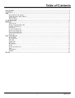
Страница 3: ...Changing Hydraulic Fluid 11 Inspection of Internal Parts 11 Tank Removal 11 Control Valve Replacement 12 Speed Control Replacement 12 Pressure Valve Replacement 12 Forward Switch Replacement 12 Power...

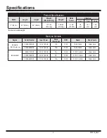
Страница 4: ...2 Machine Variants Region Serial Number Input Power Amps Full Load RPM Speed Body Panels Domestic North America 5280 10XXXX 120V 60 Hz 12A 1725 12 50 ft min Silver Vein 5280 23XXXX 120V 60 Hz 12A 1725...

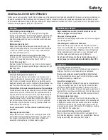
Страница 5: ...uence of drugs alcohol or any medication that may cause decreased control Keep hands away from all moving parts and tooling Wear gloves when changing tooling Remove tooling when ma chine is not in use...

Страница 6: ...IVE TOXICITY OR OTHER HARMFUL EFFECTS CONTROL DUST MIST AND FUMES AT THE SOURCE WHERE POSSIBLE IN THIS REGARD USE GOOD WORK PRACTICES AND FOLLOW THE RECOMMENDATIONS OF THE MANUFACTURER SUPPLIER OSHA N...

Страница 7: ...fluids when exposed to the proper conditions Leaking pres surized hydraulic fluids may develop a mist or fine spray that can flash or explode upon contact with a source of ignition These explosions ca...

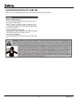
Страница 8: ...ng before disconnecting cord Unplug equipment When not in use and before changing accessories or performing maintenance unplug the machine Extension Cord Selection All cords should be sized appropriat...

Страница 9: ...0V Supply 25ft 7 5m 50ft 15m 75ft 25m 100ft 30m 150ft 45m 200ft 60m 230V Supply 50ft 15m 100ft 30m 150ft 45m 200ft 60m 300ft 90m 400ft 120m Max Amps Minimum Wire Size 8 16 AWG 1 5mm2 16 AWG 1 5mm2 16...

Страница 10: ...forward movement Damaged belt Remove front cover plate and inspect belt Damaged speed control valve Inspect speed control valve Turn counter clockwise to open valve Motor shuts off or won t start Ins...

Страница 11: ...n the fluid into Fluid will not be removed from hoses Regardless of the machine s straining system add fluid through a filter or funnel with a screen to keep fluid clean INSPECTION OF INTERNAL PARTS V...

Страница 12: ...ROL REPLACEMENT 1 Use 3 32 Allen wrench to remove metal knob 2 Use a 1 socket to remove and replace speed control valve 3 Re install metal knob PRESSURE VALVE REPLACEMENT This has been factory set and...

Страница 13: ...TION QTY PART DESCRIPTION QTY OVERALL MACHINE ADDITIONAL PARTS NOT SHOWN 1 74631 BOLT HEX FLANGE BOLT M6 16 3 2 5280 9 SPACER WHEEL 2 3 73315 BOLT FLAT HEAD SOCKET 5 16 18X1 2 4 74623 SCREW BUTTON HEA...

Страница 14: ...MP 1 12 5280 118 FITTING 90 DEGREE 1 13 5280 129 ECCENTRIC 1 14 5280 132C PULLEY PUMP 1 15 73903 KEY 3 16X3 16X2 1 4 1 16 5280 139 BRACKET HANDLE ADJUSTMENT 1 17 400324 BEARING TURNED 1 1 4ID SBLF206...

Страница 15: ...2182 COVER CAPACITOR LEESON 1 4 401698 BOX JUNCTION MOTOR 3 X 3 3 1 5 401869 GASKET FRAME JUNCTION BOX 3X3 33 1 6 401699 COVER JUNCTION BOX MOTOR 3 X 3 3 1 7 401870 GASKET COVER JUNCTION BOX 3X3 33 1...

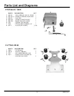
Страница 16: ...MAGNET TANK NOT SHOWN 1 6 70601 STRAINER TANK MOUNTED 1 7 72816 FITTING ELBOW 90 DEGREE 3 8 1 8 400177 OIL BULK NOT SHOWN 2 GAL PART DESCRIPTION QTY 1 5280 8 CUTTING HEAD 1 2 405950 ISOLATOR VIBRATION...

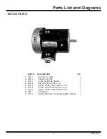
Страница 17: ...ION 2 2 6280 168 CORD POWER SJTOW 12 3 NEMA 5 15 YELLOW 27IN 1 3 72612 ASSEMBLY CORD HANDLE 14 3 NEMA L5 15R 28 1 4 5280 172A LEVER HANDLE 1 5 74650 BOLT HEXFLANGEM10 25 6 6 73502 STRAIN RELIEF STRAIG...

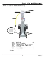
Страница 18: ...280 181 HOSE HYDRAULIC 1 4 X 32 F 90F 1 16 5700 76 HOSE HYDRAULIC 3 8 X 26 F F 1 17 6280 207 SWITCH ON OFF 1 18 6280 215 VALVE BLOCK ASSEMBLY 1 19 73002 WASHER SPLIT LOCK 1 4 4 20 73005 SCREW HEX HEAD...

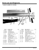
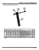
Страница 19: ...5280 11XXXX 5280 13XXXX 5280 20XXXX DESCRIPTION QTY 1 404583 028 404583 028 404583 028 Assembly Cord Handle 2 5mm 3 NEMAL6 15R 28 1 2 404313 404313 404313 Cover Handle Safety Switch 1 3 404172 Assemb...

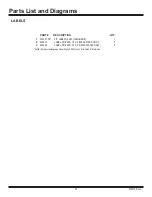
Страница 20: ...72_RevJ 1 403357 XX KIT LABELS 5280 LANGUAGE 1 2 402627 LABEL PRIVATE 1 5 X 2 5280 23XXXX ONLY 2 3 402628 LABEL PRIVATE 3 5 X 5 5 5280 23XXXX ONLY 2 PART DESCRIPTION QTY Suffix XX denotes language Non...

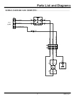
Страница 21: ...2 5mm BLU 2 5mm BRN P2 L N G 2 5mm GRN YEL 2 5mm BLU 2 5mm BRN M U1 U3 Z8 U2 U4 Z5 GROUND T F22 T F12 T F21 T F11 T F1 T M1 ON OFF SWITCH 120V SUPPLY 2 5mm BRN 2 5mm BLU 2 5mm GRN YEL G N L P1 REV A...

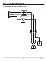
Страница 22: ...UPPLY ON OFF SWITCH UNDERVOLTAGE PROTECTED T F2 T M2 REVISIONS REV DESCRIPTION DATE ECN DR CK A INITIAL RELEASE CTW 2 25 2021 THE INFORMATION CONTAINED IN THIS DRAWING IS THE SOLE PROPERTY OF NATIONAL...

Страница 23: ...BRN P2 L N G 2 5mm GRN YEL 2 5mm BLU 2 5mm BRN GROUND T R2 T F22 T F12 T R1 T F21 T F11 GROUND 12 11 21 22 2 5mm BRN 2 5mm BLU 2 5mm GRN YEL G N L P1 Z5 U4 U2 Z8 U3 U1 M ON OFF SWITCH UNDERVOLTAGE PR...

Страница 24: ...ts List and Diagrams 24 HYDRAULICS A B P A T B HYDRAULIC MOTOR HYD PUMP FLUID TANK HYDRAULIC VALVE FWD PRESS FLOW FWD PRESS FLOW POSITIVE PRESSURE SUCTION NEGATIVE PRESS TO TOP OF TANK BLEED 402972_Re...

Страница 25: ...he negligence of seller and or the manufacturer of the product unless specifically provided herein This warranty shall not apply to any products or portions there of which have been subjected to abuse...

Страница 26: ......

Страница 27: ......

Страница 28: ...9250 Xylon Avenue N Minneapolis MN 55445 U S A Toll free 800 245 0267 Phone 763 315 5300 Fax 800 648 7124 Fax 763 535 8255 Web Site www nationalequipmentdirect com E Mail info nationalequipment com...

Отзывы: