


nash_elmo Industries GmbH
16 / 23
Order No.: 610.44436.40.000
Subject to change
Edition 09/2003
Installation
•
Use screened power supply cables if
necessary. For optimal screening, the
screen must be conductively connected over
a large area to the metal terminal box of the
drive motor with a screwed metal gland.
•
In the case of drive motors with integrated
sensors (e.g. PTC thermistors) interference
voltage can occur on the sensor cable
depending on the converter model.
•
Limit speed:
see specifications on the rating plate.
WARNING
Pump-motor units with a UL approbation may
not be operated on frequency converters in the
US without testing by a suitable test agency!
5.3 Connecting
pipes/hoses
(vacuum
pump/compressor)
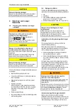
Mufflers:
The pump-motor units are delivered with
mufflers (indicated with arrows in the following
illustrations) for the inlet and discharge
connections as standard equipment.
With
single-impeller pump-motor units
, the
mufflers are already mounted on delivery.
Fig. 2: 2BH721 ... 2BH761 (single-impeller
pump-motor units)
With
two-impeller and three-impeller pump-
motor units
, the inlet-side muffler is included
loose for packaging-related reasons and must
be mounted by the operator.
Fig. 3: 2BH722 ... 2BH762 (two-impeller pump-
motor units with two-stage design)
Fig. 4: 2BH723 ... 2BH763 (three-impeller pump-
motor units with three-stage design)
WARNING
Danger from rotating impeller:
Cutting/cutting off of extremities!
The rotating impeller is accessible with the inlet
and discharge connections open!
With free entry and exit of gases, i.e. with
direct intake out of or direct feeding into the
atmosphere without piping, the following
therefore applies:
Provide the inlet and discharge connections of
the pump-motor unit either with additional
mufflers or with additional piping of a sufficient
length to prevent access to the impeller!
Connections:
To prevent foreign bodies from entering the
unit, all connections are sealed off when
delivered. Do not remove the sealing plugs
until immediately before connecting the
pipes/hoses.
The following applies for the arrangement of
the pipe/hose connections:
The
pumped gases
are sucked in via the inlet
connection (see Chapter 5.3.1, Pg. 17) and
discharged via the discharge connection (see
Chapter 5.3.2, Pg. 17).
The
rotating direction of the shaft
is marked
with an arrow on the face of the vacuum
pump/compressor cover and on the fan guard
(Fig. 1, Pg. 2, Item 7).
The
flow direction of the gases
is marked
with arrows on both connections (Fig. 1, Pg. 2,
Item 6).