W415-2107 / F / 06.23.20
EN
18
electrical information
3.5 240V hard-wire connection
A.
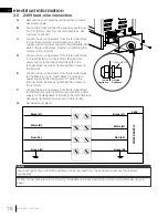
Remove the cover plate by removing the 3 screws.
Set screws aside.
B.
Add a strain relief and feed the supply wires through
the 7/8” (22mm) hole from the terminal block. Use
minimum 14AWG/3.
C.
Loosen the securing screws from the terminal block
for the Green (G) wire. Insert Green (G) or bare
copper wire from power supply to the designated (G)
slots in the terminal block. Secure by tightening the
screws on the (G) slots.
D.
Loosen the securing screws from the terminal block
for the White (N) wire. Insert White (N) wire from
power supply to the designated (N) slots in the
terminal block. Secure by tightening the screws on
the (N) slots.
E.
Loosen the securing screws from the terminal block
for the Black (L1) wire. Insert Black (L1) wire from
power supply to the designated (L1) slots in the
terminal block. Secure by tightening the screws on
the (L1) slots.
F.
Loosen the securing screws from the terminal block
for the Red (L2) wire. Insert Red (L2) wire from power
supply to the designated (L2) slots in the terminal block.
Secure by tightening the screws on the (L2) slots.
G.
Re-install cover plate.
Leave enough wiring so that the appliance can be removed from the enclosure to access the hardwire
connections.
note:
If 240V connections are wired incorrectly, the appliance will not function and will emit an audible warning (i.e.
beep).
Green (G)
Red (L2)
White (N)
Black (L1)
Black (L1)
White (N)
Green (G)
240V
POWER SUPPL
Y
Red (L2)
Inside
Appliance
Strain Relief
Outside
Appliance


