background image

W415-0616 / E / 10.08.08

46

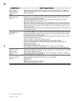
SYMPTOM

TEST SOLUTION

The 200°F (93°)

high limit tempera-

ture sensor has 

tripped 

The heater will not 

turn off

The heater keeps 

going out

Excessive carbon 

build up in the 

firebox, low heat 

out put

Unit is burning dirty 

and lazy

-   Reset the sensor and determine whether it was the convection blower or 160°F (71°C) temperature 

    sensor failure. Bypass the 160°F (71°C) sensor. Does the convection blower not come on high? If no 

    than replace the blower.

-   Disconnect one of the brown wires from the exhaust temperature sensor and if the unit continues to 

    operate, contact your local dealer for service.

-   Compare the wiring diagram to the start control module and the connections to the 140°F (60°C) 

    temperature sensor. Check the connections.

-   Remove one of the brown wires from the 140°F (60°C) temperature sensor. The heater should be shut 

    down right away as long as the start button was not pressed within 15 minutes of this test. If the heater 

    shuts down within 15 minutes, replace the 140°F (60°C) sensor. If the heater does not shut down in 15 

    minutes, test the switch.

-   The heater must be cold to test the switch. Pull the plug, then plug the heater back in. If the heater fails 

    to start, replace the switch.

-   Due to different installation set ups, length and size of venting and fuel quality, the low feed setting from 

    the factory will not always be correct. It may be necessary to   experiment with feed rate vs air control. 

    (For example, #2 may be your lowest setting). 

-   If the heater goes out and leaves fresh unburned pellets or cigarette-like ashes in the burn pot, the fire 

    is going out before the heater shuts off. 

-   Check to see if the air control rod is in the correct position. 

-   Turn the feed rate up slightly (poor quality pellets will require slightly higher settings).

-   Check to see if the heater needs a more complete cleaning as well as the burn pot, venting, etc...

-   Was there a power failure?

-   Contact your local dealer for service

-   If the heater goes out and there are no pellets in the 

burn pot, the auger may be slipping

.

-   See "The auger motor will not function normally" and "The exhaust blower will not function normally".

-   Check quality of pellets. Even pellets from the same manufacturer can vary in quality since the materials 

    they use to form pellets may also vary.

-   Moisture content of pellets too high. Pellets must be stored in a dry place. Areas such as a garage are 

    too damp causing pellets to absorb moisture. 

-   Check that all exhaust and intake pathways are clear of any obstructions.

-   Burn pot is clean.

-   Pellets are dry.

-   Venting and terminal are clear of obstructions.

-   Exhaust blower is operation and is clean.

TP - PEllET TROUblE ShOOTING 3

Содержание Auburn NPS40

Страница 1: ...W415 0616 E 10 08 08 1 W415 0616 E 10 08 08 10 00 ...

Страница 2: ...mum inside vertical clearances 18 4 7 4 class a chimney retrofit 19 4 7 5 hearth mount installation 19 4 7 6 installation into a masonry fireplace 20 5 0 stove installation 21 5 1 minimum clearance to combustibles 21 5 1 1 straight installation 21 5 1 2 corner installation 21 6 0 insert installation 22 6 1 Masonry fireplace installation 22 6 2 factory built METAL fireplace 23 6 3 installation into...

Страница 3: ...t 32 9 3 1 vacuum hopper 32 9 3 2 soot and fly ash formation 33 9 3 3 clean the vertical exhaust duct 33 9 3 4 Clean exhaust housing insert only 33 9 3 5 Clean the exhaust blower 33 9 3 6 check all seals 34 9 3 7 clean the vent 34 9 4 in the event of a jammed auger 34 10 0 Normal operating sounds 35 11 0 Wiring diagram 36 12 0 replacements 37 12 1 Common replacement parts 40 12 2 nps40 replacement...

Страница 4: ...s recommended that the pellet vent joints be sealed with a minimum 500 F 260 C silicone sealant Install according to the vent manufacturers instructions Your heater requires periodic maintenance and cleaning Failure to maintain your heater may lead to smoke spillage in your home Allow the heater to cool before performing any maintenance or cleaning Ashes must be disposed in a metal container with ...

Страница 5: ...an adapter plug or sever the grounding prong Do not route the electrical cord underneath in front of or over the heater When installed in a mobile home the heater must be bolted to the floor have outside air and NOT BE INSTALLED IN THE BEDROOM Per H U D requirements Check with local building officials The exhaust system should be checked and cleaned once a year minimum for any build up of soot or ...

Страница 6: ...ranty NAPOLEON may at its discretion fully discharge all obligations with respect to this warranty by refunding to the original warranted purchaser the wholesale price of any warranted but defective parts After the first year NAPOLEON will not be responsible for installation labour or any other costs or expenses related to the reinstallation of a warranted part and such expenses are not covered by...

Страница 7: ...nter line of air intake In order to install flashing flush to finished wall and centered within the opening the front opening of the fireplace or enclosure must be this wide 15 Stand off s Center line of air intake Center line of exhaust Center line of insert 1 1 4 Figure 1 3 2a 1 3 dimensions 1 3 1 Nps40 1 3 2 npi40 complete with ni800 flashing Figure 1 3 1b Figure 1 3 2b Figure 1 3 2c ...

Страница 8: ... line of air intake In order to install flashing flush to finished wall and centered within the opening the front opening of the fireplace or enclosure must be this wide 28 1 8 Center line of insert 16 1 2 Center line of air intake Center line of exhaust 1 5 8 14 1 4 10 5 8 Stand offs 1 3 3 npi40 complete with ak9 adapter and cisk flashing Figure 1 3 3b Figure 1 3 3c ...

Страница 9: ...ir intake In order to install flashing flush to finished wall and centered within the opening the front opening of the fireplace or enclosure must be this wide 29 3 16 46 7 16 2 3 16 15 5 8 Center line of air intake Center line of exhaust Center line of insert Stand offs 1 3 4 npi40 complete with ak8 adapter and gicsk flashing Figure 1 3 4a Figure 1 3 4b Figure 1 3 4c ...

Страница 10: ...INIMUM MANTEL CLEARANCES Drywall or other combustible material See the sections GENERAL VENTING and INSTALLATION See the section MINIMUM FRAMING DIMENSIONS Side Wall See the section MINIMUM CLEARANCES TO COMBUSTIBLES See the section INSTALLATION INTO A BUILT IN ENCLOSURE Figure 1 4 ...

Страница 11: ...use any other type of fuel such as fire logs or fire starting pellet as this will void the warranties stated in this manual The performance and heat output of the pellet heater is directly related to the quality and moisture of the pellets Store pellets in a cool dry area to prevent moisture absorption WARNING It is important to select and use only pellets that are dry and free of dirt or any impu...

Страница 12: ... the event that the temperature of the heater approaches an unsafe operating temperature this switch will shut down the pellet feed which will eventually shut down the unit If this happens it is important to find out why the unit overheated Contact your local dealer LOW LIMIT SWITCH This switch will automatically shut down the heater if the fire goes out HOPPER DOOR INTERLOCK Your heater is equipp...

Страница 13: ...g with installation Before installing we recommend placing the heater outside and load 5 pounds of pellets inside the hopper Plug the heater in and let it run on HIGH until the pellets run out This will cure the paint and burn off the oils on the steel thereby minimizing any smell inside the home WARNING Read entire manual before you install or use this heater Failure to follow the instructions ma...

Страница 14: ...chimney termination must have a rain cap or down turned elbow to prevent the water from entering and be located so that it will not become plugged by snow or other material Outside air is mandatory for a combustible built in enclosure install Installation into a manufactured home or mobile home should be installed in accordance with the Manufactured Home Construction and Safety Standard Title 24 C...

Страница 15: ...e some natural draft This is to help prevent the possibility of smoke or odour during the appliance shut down or in the event of a power outage Horizontal sections must have a 1 4 rise every 12 of travel if longer than 3 The pellet vent connections must be sealed with HI Temp RTV Silicone and screwed together with at least 3 3 8 long stainless steel screws Seal each vent section by injecting a lib...

Страница 16: ... wall or protruding combustible ob structions vent chase etc Clearance to a non mechanical air supply inlet to the building or a combustion air inlet to any other appliance Clearance to a mechanical air supply inlet Clearance above a paved sidewalk or paved driveway located on public property Clearance under a veranda porch deck or balcony Clearance above the roof Clearance from an adjacent wall i...

Страница 17: ... installation Wall Thimble Outside Air Floor Protection 12 Minimum Outside Air Recommended 6 Minimum 3 Minimum 17 3 8 Wall Thimble 11 3 4 5 Maximum 4 7 stove Venting installation examples 4 7 1 horizontal exhaust through wall installation Figure 4 6 Figure 4 7 1 ...

Страница 18: ...ical rise and horizontal termination Outside air Recommended Installation showing inlet of out side air in ventilated crawl space Ceiling Support Vent must maintain 3 clearance to combus tibles Vertical Cap Roof Flashing Storm Collar Floor Protection 3 2 4 7 3 minimum inside vertical clearances Figure 4 7 2 Figure 4 6 3 ...

Страница 19: ...ust maintain 3 clearance to combustibles Roof Flashing Storm Collar Floor Protection 3 2 Vertical Cap 4 7 4 class a chimney retrofit Floor Protection 6 MIN Clean out tee Outside Air Recommended Storm Collar Vertical Cap Chimney Cap Bring outside air to the stove Pellet Liner Flue Cover Pellet Vent 4 7 5 hearth mount installation Figure 4 7 4 Figure 4 7 5 ...

Страница 20: ...signs of deterioration If necessary have any repair work done by a qualified profes sional before installing the heater A Remove the fireplace damper or fasten it permanently open B Measure the throat of the fireplace and mark this shape on a piece of 24 gauge sheet metal flue cover Cut a hole sized for the pellet liner to lie directly below the fireplace flue opening Allow two inches of material ...

Страница 21: ...s determined by the upward turning elbow or Tee It will vary in depth depending on the brand of pellet vent used it is approximately 5 Before placing the heater connect the elbow or Tee and allow for the minimum 3 clearance to the combustible wall 5 1 2 corner installation Through the Wall Installations Interior Vertical Vents 5 1 1 straight installation Figure 5 1 1a Figure 5 1 1b Figure 5 1 2a F...

Страница 22: ...e or other signs of deterioration If necessary have any repair work done by a qualified professional before installing the heater A Remove the fireplace damper or fasten it permanently open B Measure the throat of the fireplace and mark this shape on a piece of 24 gauge sheet metal flue cover Cut a hole sized for the pellet liner to lie directly below the fireplace flue opening Allow two inches of...

Страница 23: ...installing the heater A Remove the fireplace damper or fasten it permanently open B Measure the throat of the fireplace and mark this shape on a piece of 24 gauge sheet metal flue cover Cut a hole sized for the pellet liner to lie directly below the fireplace flue opening Allow two inches of material for a flange on all sides and cut to these measurements Bend down the flanges If you have never do...

Страница 24: ...s well as a minimum of six inches in front and to both sides of the heater A Install floor protection B Frame structure maintaining minimum clearances Locate and frame openings for both the exhaust and outside air Outside air is mandatory for Enclosure installations C Refer to the vent manufacturer s installation instructions and to General Venting section Connect the vent D Install flashing See N...

Страница 25: ...rning do not remove 27 Stand offs 3 all around Refer to vent manufacturer s instructions 2 1 4 6 3 8 Minimum Figure 6 3 2 6 3 3 minimum clearance to combustibles Side wall to heater 8 Maximum mantel depth 10 Mantel to top of heater 8 Top facing to heater 6 3 8 Side facing to heater 6 Floor protection 6 8 MIN Side Wall 6 6 8 MIN 10 10 Mantel Floor Protection Minimum 6 in front of door and to either...

Страница 26: ...tallation instructions and see GENERAL VENTING section Connect the vent cap to vent 6 4 1 6 4 2 6 4 3 6 5 vertical liner installation If you plan on connecting outside air it is recommend to do so at this time Remove the fireplace damper or fasten it permanently open Measure the throat of the fireplace and mark this shape on a piece of 24 gauge sheet metal flue cover Cut a hole sized for the pelle...

Страница 27: ...avec les vis déserrées les sections de la gar Reserrez les vis en é les 2 sections Fixez la adjacente Faites de avec le côté opposé Re fermement toutes The three pieces of trim are assembled in the same man ner as a picture frame Place the corner brackets with screw loosened into the trim sections Tighten the screw spreading the two pieces apart Attach the adjoining section Repeat with the opposit...

Страница 28: ...nd close the viewing door Heater may be hot Other than placing a handful of pellets in the burn pot for lighting manually never feed pellets through the glass viewing door An OVERFIRE condition could occur if more pellets enter the firebox then what the feed tube can deliver Pellets must only be burned within the burn pot WARNING 8 1 proper pellet loading TP PROPER PELLET LOADING TP LIGHTING HEATE...

Страница 29: ... the amount of heat output The switch has a scale dial from 1 through 5 At setting 5 the pellet feed rate is the greatest Blower Speed Dial By adjusting the Blower Speed dial you will vary the rate of airflow into the room by varying the speed of the convection blower When you first start the heater it should be placed in the OFF position in order to heat up the unit as quickly as possible Once th...

Страница 30: ...MAKE SURE PELLETS ARE NOT PILING UP or CLEANING THE BURNPOT sections TP MAIN VIEWING DOOR_PELLET TP DISPOSAL OF ASHES_PELLET TP INSPECT BURN POT_PELLET TP CARE OF GLASS Figure 9 1 1a Figure 9 1 1b Figure 9 1 3 DO NOT CLEAN GLASS WHEN HOT DO NOT USE ABRASIVE CLEANERS TO CLEAN GLASS OR PLATED PARTS Buff lightly with a clean dry soft cloth Clean the glass after the first 10 hours of operation with a ...

Страница 31: ...the build up of ash on the heat exchange tubes Keep the viewing door closed so the fly ash does not enter the room NOTE More frequent cleaning may be required depending upon pellet quality The front edge of the hopper lid becomes very hot do not touch the area below the handle This rod becomes very hot during operation Wait till heater has cooled completely or you must wear heat resistant gloves w...

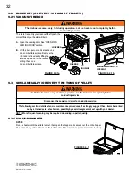
Страница 32: ...annually or every two tons of pellet 9 3 1 vacuum hopper The firebox becomes very hot during operation Let the heater cool completely before conducting service Disconnect the power cord prior to conducting service The following section details extensive maintenance procedures We strongly suggest these items be carried out by a trained service technician possibly by a service agreement set up with ...

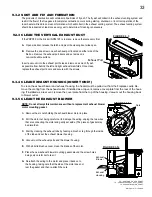
Страница 33: ... from the fireplace cavity Re move the venting from the exhaust collar If installed as a top vent remove cover plate from the rear of the hous ing If installed as a rear vent remove the cover plate from the top of the housing Vacuum out the housing back to blower outlet 9 3 4 Clean exhaust housing insert only 9 3 5 Clean the exhaust blower NOTE Do not attempt this maintenance without a replacement...

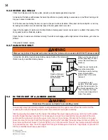
Страница 34: ...ve Accumulation greater than 1 4 must be removed On vertically vented systems the dirtiest portion is often the point where the vent turns upwards ex the Tee Remove the clean vent cover and inspect and clean if necessary Whenever any portion of the pellet vent is disconnected the joints must be re sealed with RTV 500 F silicone sealant WARNING TP SEALS_PELLET TP CLEAN VENT_PELLET Figure 9 3 7 9 4 ...

Страница 35: ...W415 0616 E 10 08 08 35 10 0 Normal operating sounds TP OPERATING SOUNDS_PELLET Figure 10 0 ...

Страница 36: ...rey Red Grey Grey Pellet Feed Dial Auger Cycle Light Start Switch Blower Dial Ignitor Auger Control High Limit Switch Blower over ride Switch Convection Blower Auger Motor Ignitor Switch Combustion Blower Vacuum Switch Low Limit Switch Slip on 250 FI 1 wire Slip on 250 FI 2 wires Slip on 250 FI 2 wires Power Cord Black White Black Power Control Brown Grey Purple Control Panel Hopper Switch Blue Bl...

Страница 37: ...LOW LIMIT SWITCH 140 F 80 C 2 W660 0053 OVER RIDE SWITCH 160 F 71 C 3 W660 0054 IGNITION SWITCH 120 F 60 C 4 W660 0055 HIGH LIMIT SWITCH 200 F 93 C 5 W660 0056 VACUUM SWITCH 6 W380 0020 CONTROL KNOB 7 W195 0004 POWER CORD 8 W435 0009 AUGER MOTOR 9 W062 0021 CONVECTION BLOWER 10 W062 0022 COMBUSTION BLOWER 11 W290 0111 COMBUSTION BLOWER MOUNTING GASKET 12 W290 0120 COMBUSTION BLOWER MOTOR MOUNTING ...

Страница 38: ...ST COVER 52 W290 0122 EXHAUST GASKET 53 W010 1673 RIGHT LOUVRE ASSEMBLY 54 W010 1685 LEFT LOUVRE ASSEMBLY 55 W010 1567 AIR CONTROL NPS40 COMPONENTS REF PART NO DESCRIPTION 56 W010 1508 WELDED TOP ASSEMBLY 57 W010 1527 SIDE DOOR ASSEMBLY 58 W010 1529 HOPPER DOOR ASSEMBLY 59 W010 1667 ASH PAN ASSEMBLY 60 W010 1668 PEDESTAL SIDE DOOR ASSEMBLY 61 W035 0191 PEDESTAL BASE 62 W555 0059 AIR CONTROL ROD 63...

Страница 39: ...ET NPS40 ACCESSORIES REF PART NO DESCRIPTION 80 NPHE 40 HOPPER EXTENSION INCREASES HOPPER CAPACITY FROM 55 LBS TO 100 LBS PELLETS NPI40 ACCESSORIES REF PART NO DESCRIPTION 81 NI800 8 BLACK FLASHING WITH BLACK TRIM 82 GICSK ARCHED CAST IRON SURROUND 83 AK8 ADAPTOR KIT REQ D FOR GICSK 84 CISK CAST IRON SURROUND KIT BLACK 84 CISKK CAST IRON SURROUND KIT ENAMEL BLACK 84 CISKN CAST IRON SURROUND KIT MO...

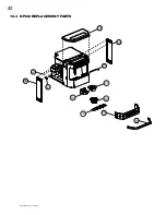
Страница 40: ...W415 0616 E 10 08 08 40 12 1 Common replacement parts ...

Страница 41: ...W415 0616 E 10 08 08 41 57 38 61 44 58 65 57 64 56 58 59 60 66 15 31 40 54 53 67 12 2 nps40 replacement parts ...

Страница 42: ...W415 0616 E 10 08 08 42 69 28 38 70 41 40 53 54 75 71 69 72 12 3 Npi40 replacement parts ...

Страница 43: ...W415 0616 E 10 08 08 43 74 78 76 5 79 47 46 AK9 PRPP40 NPL41 75 81 83 85 NI800 AK9 AK8 12 4 common accessory parts 12 5 npi40 accessory parts ...

Страница 44: ...eck all gasket seals Vent connections all sealed Unit has failed to reach 140 F within 15 minutes and the blower has shut off Restart unit NOTE A minimal amount of smoke is normal during the start up process Remove the left side access panel and check all connections against the wiring diagram For the insert remove from cavity Apply 115V AC directly to the exhaust blower and if the motor does not ...

Страница 45: ...ectly Replace the blower controller if the motor runs The convection blower has failed if the motor does not run Replace the blower If the convection blower runs on high at all times no control with the blower controller check the connections from the 160 F 71 C sensor located on the upper left side on the rear of the fire wall and convection blower controller to the blower Disconnect one of the w...

Страница 46: ...different installation set ups length and size of venting and fuel quality the low feed setting from the factory will not always be correct It may be necessary to experiment with feed rate vs air control For example 2 may be your lowest setting If the heater goes out and leaves fresh unburned pellets or cigarette like ashes in the burn pot the fire is going out before the heater shuts off Check to...

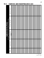
Страница 47: ... 08 47 14 0 Service and maintenance log Appliance Service History This fireplace must be serviced annually depending on usage Date Service Technician Name Service Performed Special Concerns Dealer Name TP SERVICE HISTORY ...

Страница 48: ...W415 0616 E 10 08 08 48 NOTES 15 0 notes TP NOTES ...

Отзывы: