background image

W415-4020 / 08.09.21

78


FR

information générales

1.1  plaque d'homologation / l'emplacement d'instruction d'allumage

Cette illustration est à titre de référence seulement. Consultez la 

plaque d’homologation pour obtenir l’information précise.

La plaque d’homologation et les instructions d’allumage sont fixées au câble et situé derrière le panneau de 

l'appareil de contrôle. Soulevez le panneau d'accès et le panneau du contrôle et loin de l'appareil. Avec le câble 

à la fin de l'ampoule de la fente, remuer la plaque signalétique sur en faisant attention de ne pas déchirer les 

instructions.

Certified to Canadian and American National Standards: 

CSA 2.22-XXXX / ANSI Z21.50-XXXX for Vented Decorative Gas Appliances

Certifié selon les normes Nationales Canadiennes et Américaines: 

CSA 2.22-XXXX / ANSI Z21.50-XXXX pour les Appareils à gaz décoratif à évacuation

Direct vent, vented gas fireplaces. Approved for bedroom, bathroom and bed-sitting room installation. Suitable for mobile home installation, if installed in accordance with the current 

standard CAN / CSA Z240MH Series gas equipped mobile homes in Canada, or, in the United States, the 

Manufactured Home Construction and Safety Standard, Title 24 CFR, Part 

3280

. When this US Standard is not applicable, use the 

Standard for Fire Safety Criteria for Manufactured Home Installations, Sites and Communities

, ANSI / NFPA 501A. This appliance 

must be installed in accordance with local codes, if any; if none, follow the current ANSI Z223.1 or CSA B149. 

For use with barrier WXXX-XXXX. Follow installation instructions.

Foyer à gaz ventilé. Homologué pour installation dans une chambre à coucher, une salle de bain et un studio. Approprié pour installation dans une maison mobile si son installation 

conforme aux exigences de la norme CAN / CSA Z240MH Séries de maisons mobile équipées au gaz en vigueur au Canada, ou, aux États-Unis selon la norme 

24 CFR, Part 3280, 

Manufactured Home Construction and Safety Standard

. Dans le cas ou cette norme d’États-Unis n’est pas pertinentes, utiliser la norme 

NFPA 501A, Fire Safety Criteria for Manufactured 

Home Installations, Sites and Communities

. Installer l’appareil selon les codes ou règlements locaux ou, en l’absence de tels règlements, selon les codes d’installation ANSI Z223.1 ou 

CSA B149 en vigueur. 

Utiliser uniquement avec l’écran WXXX-XXXX. Suivre les instructions d’installation.


9700539 (WSL) 

4001658 (NAC) 

4001657 (NGZ) 

4001659 (WUSA)

WOLF STEEL LTD. 

24 Napoleon Road, Barrie, ON, L4M 0G8 Canada


  XXXX 


XXXX 


XXXX 


XXXX

MODEL / MODÈLE

Altitude

Input

Reduced Input

P4

Élévation

Alimentation

Alimentation Réduite

P4

Manifold Pressure: 

3.5” w.c. (NG)

Minimum Supply Pressure: 

4.5” w.c. (NG)

Maximum Supply Pressure: 

7”* w.c. (NG)

Pression au Collecteur: 

3,5” d’une colonne d’eau (GN)

Pression d’Alimentation Min.: 

4,5” d’une colonne d’eau (GN)

Pression d’Alimentation Max.: 

7” ** d’une colonne d’eau (GN)

** Maximum inlet pressure not to exceed 13”.

Manifold Pressure: 

10” w.c. (P)

Minimum Supply Pressure: 

11” w.c. (P)

Maximum Supply Pressure: 

13”* w.c. (P)

Pression au Collecteur: 

10” d’une colonne d’eau (P)

Pression d’Alimentation Min.: 

11” d’une colonne d’eau (P)

Pression d’Alimentation Max.: 

13” * d’une colonne d’eau (P)

** Pression d’alimentation maximale ne devait pas dépasser 13”.

0-XXXXft (0-XXXXm)

Minimum clearance to combustible materials: 

Top, sides & back: per standoff spacers for framing and finishing 

materials. For non-combustible framing and finishing materials, 

see installation manual.

Top X” 


Floor X” 


Sides  X”

Back X”

Vent top X”

Vent sides & bottom X”

Recessed depth X”

*** Mantel X” from appliance opening

Dégagements minimaux des matériaux combustibles: 

Dessus, côtés et arrière: selon les espaceurs de dégagements 

pour les matériaux d’ossature selon le manuel du propriétaire 

pour les matériaux de finition.

                    Dessus X” 

                  Plancher X“

Côtés X”

Arrière X“

Dessus du conduit d’évent X”

Côtés et dessous du conduit d’évent X” 

Profondeur d’encastré une face X” 

*** Tablette X” de l’ouverture de l’appareil

WARNING

Do not add any material to the appliance which will come in contact with the 

flames, other than that supplied by the manufacturer with the appliance.

AVERTISSEMENT

:  

N’ajoutez pas à cet appareil aucun matériau devant entretien 

contact avec les flammes autre que celui qui est fourni avec cet appareil par le fabricant.

*** Maximum horizontal extension: 

X”. See installation manual for 

greater extensions, minimum vent 

lengths and maximum vent lengths.

*** L’extension horizontale maximale: X”. 

Référez au manuel d’installation pour des 

extensions plus grandes, les longueurs 

d’évacuation minimaux et maximum.

The appliance must be vented using the appropriate Napoleon vent kits. See installation 

manual for venting specifications. Proper reinstallation and resealing is necessary after servicing 

the vent-air intake system.

L’appareil doit être ventilé à l’aide de l’ensemble d’évacuation propre à Napoleon. Référez au 

manuel d’installation pour les spécifications d’évacuation. Il est nécessaire de bien réinstaller et 

resceller l’évacuation après avoir executer l’entretien du système de prise d’air.

Serial Number / N° de Série: 

W385-XXXX

REFERENCE# 161746

XXXX

VENTED DECORATIVE GAS APPLIANCE: NOT A SOURCE OF 

HEAT, NOT INTENDED FOR USE AS A HEATING 

APPLIANCE, NOT FOR USE WITH SOLID FUEL.

APPAREIL À GAZ DÉCORATIF À ÉVACUATION: N’EST PAS 

UNE SOURCE DE CHALEUR; N’EST PAS DESTINÉ À ÈTRE 

UTILISÉ COMME UN APPAREIL DE CHAUFFAGE; NE 

CONVIENT PAS AUX COMBUSTIBLES SOLIDES.

FOR USE WITH GLASS DOORS CERTIFIED WITH THIS APPLIANCE ONLY.

POUR UTILISATION UNIQUEMENT AVEC LES PORTES EN VERRE 

CERTIFIÉES AVEC L’APPAREIL.

XX,XXX 


XX,XXX

XX,XXX 


XX,XXX

For natural gas when equipped with No. XX drill size orifice.

For propane when equipped with No. XX drill size orifice.

Convient au gaz naturel quand l’appareil est muni d’un injecteur de diamètre no. XX.

Convient au propane quand l’appareil est muni d’un injecteur de diamètre no. XX.

Electrical rating: 115V, 60HZ. Less than 12 amperes.

Spécifications électriques: 115V, 60HZ. Moins de 12 ampère.

XX.X% 


XX.X%


  XXXX 


XXXX 


XXXX 


XXXX

ÉCHANTILLON

!

AVERTISSEMENT

•  Laisser refroidie l'appareil avant d'effectuer un entretien ou un nettoyage.

La plaque d’homologation doit rester avec l’appareil à tout instant. Il 

ne doit pas être enlevé.

note:

L'écran de protection doit être enlevée pour accéder la plaque d'homologation / instruction d'allumage.

note:

Cet appareil doit être effectuée en respectant les directives du fabricant et le Manufactured Home Construction 

and Safety Standard, Title 24 CFR, Part 3280, aux États-Unis, ou les normes actuelles pour les maisons 

mobiles, CAN/CSA Z240 SÉRIE MH au Canada. Cet appareil ne doit être utilisé qu’avec le type de gaz indiqué 

sur la plaque d’homologation. 

Cet appareil homologué pour les maisons mobiles et préfabriquées possède des éléments de fi xation. L’appareil est 

muni de deux trous de 

¼

” (6,4mm) de diamètre, situés aux coins avant, gauche et droit de la base. Fixez à l’aide des 

attaches appropriées, insérées dans les trous de la base. Pour les produits autoportante, contactez votre revendeur 

agréé / distributeur permettant l’ensemble de sécurisation. Lors d’une installation dans une maison mobile, l’appareil 

doit être fi xé au plancher. Éteignez toujours la veilleuse et l’alimentation en gaz à la source avant de déplacer la 

maison mobile. Après avoir déplacé la maison mobile et avant d’allumer l’appareil assurez-vous que les bûches sont 

placées correctement.

Cet appareil est certifi é pour être installé dans une maison mobile installée de façon permanente, sauf si les 

codes locaux l’interdisent. 

Cet appareil ne doit être utilisé qu’avec le type de gaz indiqué sr la plaque d’homologation. On ne peut utiliser 

cet appareil avec d’autres types de gaz, sauf si un ensemble de conversion certifi é est utilisé. 

Ensembles de conversion

L’appareil pour maison mobile peut être converti au gaz natural (GN) ou au propane (P).

Pour effectuer une conversion, veuillez consulter votre détaillant autorisé. 

20.1

note:

Trousse de conversions ne sont pas disponibles pour les appareils de d’évent libre.

1.2  installation dans une maison mobile

Содержание Ascent BHD4PFCNA

Страница 1: ...lier from a neighbour s phone Follow the gas supplier s instructions If you cannot reach your gas supplier call the fire department Installation and service must be performed by a qualified installer...

Страница 2: ...touching hot surfaces Even after the appliance is off it will remain hot for an extended period of time Check with your local hearth specialty dealer for safety screens and hearth guards to protect ch...

Страница 3: ...s barrier for this appliance Installation and repair should be done by a qualified service person It is imperative that control compartments burners and circulating air passageways of the appliance b...

Страница 4: ...installation 34 9 0 operation 35 10 0 operating instructions 36 10 1 operating instructions for your safety read before operating 36 10 2 lighting instructions 36 11 0 finishing 37 11 1 shipping brack...

Страница 5: ...of Installation Location of appliance Installer Dealer Distributor contact number Serial Model Product Codes Media type Fuel type BHD4PNA Logs Natural Gas BHD4PPA Logs Propane BHD4STNA Logs Natural Ga...

Страница 6: ...d using a hair dryer or similar heat source This appliance is a decorative product It is not a source of heat and not intended to burn solid fuel If utilizing one of Wolf Steel s trim or surround kits...

Страница 7: ...led combustion product The installation must conform with local codes or in absence of local codes the National Gas and Propane Installation Code CSA B149 1 in Canada or the National Fuel Gas Code ANS...

Страница 8: ...xtension horizontale maximale X R f rez au manuel d installation pour des extensions plus grandes les longueurs d vacuation minimaux et maximum The appliance must be vented using the appropriate Napol...

Страница 9: ...3mm 5 127mm 1213 16 325mm 251 8 638mm RIGHT SIDE LEFT SIDE RIGHT SIDE LEFT SIDE 79 16 192mm ELECTRICALINLET 79 16 192mm GAS INLET 21 16 53mm 343 16 868mm 45 1143mm 381 4 841mm 79 16 192mm ELECTRICALIN...

Страница 10: ...DNA Wolf Steel www mtlfab com Direct Vent Pro Simpson DuraVent W175 0170 Wolf Steel www duravent com Pro Form BDM N A BDM www dalsinmfg com Direct Temp Selkirk 5DT AAN Selkirk www selkirkcorp com Vent...

Страница 11: ...TV or a suitable aluminum tape that covers each joint in the vent system entirely around its circumference This will ensure the best performance in every application and avoids per formance or condens...

Страница 12: ...quired the appliance must have a minimum vertical rise off the appliance of 57 144 8cm On all horizontal vent runs ensure that the vent pipe does not slope downward When terminating vertically the ver...

Страница 13: ...ent length is 10 3 1m for a fireplace and 8 2 4m for a stove 8 2 38 1 4 97 2cm 24 61cm MIN REGARDLESS OF HORIZONTAL VENT LENGTH 12 30 5cm MIN TO GRADE 3 2 2 reduced vent clearance to combustibles The...

Страница 14: ...ter to the appliance collars X3 X3 5 6 3 3 converting from 5 8 to 4 7 venting Use Mill Pac to seal adapter to the appliance collars Use red RTV silicone sealant to seal adapter to the appliance collar...

Страница 15: ...arance from an adjacent wall including neighbouring buildings P 8 2 4m 8 2 4m Roof must be non combustible without openings Q 3 0 9m 3 0 9m See chart for wider wall dimensions R 6 1 8m 6 1 8m See char...

Страница 16: ...rise to maximum of 40 feet 12 2m Horizontal run vertical rise to maximum of 40 feet 12 2m Vertical Termination 11 1 For the following symbols used in the venting calculations and examples are greater...

Страница 17: ...onfigurations requiring more than two 90 elbows the following formulas apply Formula 1 HT VT Formula 2 HT VT 40 feet 12 2m Example V1 8 FT 2 4m VT V1 8 FT 2 4m H1 2 5 FT 0 8m H2 2 FT 0 6m HR H1 H2 2 5...

Страница 18: ...5 feet 7 5m Example V1 4 FT 1 2m V2 1 5 FT 0 5m VT V1 V2 4FT 1 2m 1 5FT 0 5m 5 5 FT 1 7m H1 2 FT 0 6m H2 1 FT 0 3m H3 1 FT 0 3m H4 1 5 FT 0 5m HR H1 H2 H3 H4 2FT 0 6m 1FT 0 3m 1FT 0 3m 1 5FT 0 5m 5 5...

Страница 19: ...0 feet 12 2m Example V1 5 FT 1 5m V2 10 FT 3 1m VT V1 V2 5 FT 1 5m 10 FT 3 1m 15 FT 4 6m H1 3 FT 0 9m H2 2 5 FT 0 8m HR H1 H2 3FT 0 9m 2 5FT 0 8m 5 5 FT 1 7m HO 03 one 45 three 90 elbows 135 03 45 270...

Страница 20: ...03 45 270 135 5 4 FT 1 6m HT HR HO 8FT 2 4m 5 4FT 1 6m 13 4FT 4 1m HT VT 13 4FT 4 1m 2 5FT 0 8m 15 9FT 4 8m Formula 1 HT 3VT 3VT 3FT 0 9m x 2 5FT 0 8m 7 5FT 2 3m 13 4 FT 4 1m 7 5 FT 2 3m Since this fo...

Страница 21: ...gging or loose insulation or framing and other combustible materials Block opening into the chase to prevent entry of blown in insulation Make sure insulation and other materials are secured When cons...

Страница 22: ...8 56 2cm MAX 24 1 8 61 3cm B MIN 42 1 2 108cm MAX 43 1 2 110 5cm 4 1 framing 4 1 1 see thru framing BHD4ST_A 4 1 2 peninsula framing BHD4P_A All framing dimensions are based on the finishing material...

Страница 23: ...um clearance to combustible enclosures 4 2 1 see thru BHD4ST_A 4 2 2 peninsula BHD4P_A Within the appliance enclosure a minimum 3 76mm clearance between the top of the vent pipe and combustible materi...

Страница 24: ...nt components a minimum of 3 screws must also be used to ensure the connection cannot slip off Do not clamp the flexible vent pipe Risk of fire explosion or asphyxiation Improper support of the entire...

Страница 25: ...stop assembly to the hole and secure using 4 screws B Once the vent pipe is installed in its final position apply red RTV silicone W573 0002 not supplied between the pipe and the firestop Bend the tab...

Страница 26: ...ng that the venting system passes through Apply a bead of caulking all around and place a firestop spacer over the vent shield to restrict cold air from being drawn into the room or around the firepla...

Страница 27: ...plied However the high temperature sealant W573 0007 Mill Pac not supplied must be used on the joint connecting the inner flex pipe and the exhaust flue collar Use only approved flexible vent pipe kit...

Страница 28: ...the fireplace couple them together as illustrated The vent system must be supported approximately every 3 feet 0 9m for both vertical and horizontal runs Use non combustible strapping to maintain the...

Страница 29: ...by sealing with caulking Where possible cover the sides and top edges of the flashing with roofing material F Aligning the seams of the terminal and air terminal connector place the terminal over the...

Страница 30: ...shall be in compliance with local codes In the absence of local codes use the current CSA22 1 Canadian Electric Code in Canada or the current National Electric Code ANSI NFPA NO 70 in the United Stat...

Страница 31: ...ur shoulder screws This will allow you to easily access the battery housing C Locate the battery housing inside the valve compartment D Install 2 D alkaline batteries not supplied into the battery hou...

Страница 32: ...o not use any other type of battery pack note BATTERY HOLDER GAS VALVE PILOT ASSEMBLY IGNITION MODULE PILOT GAS LINE I S AC ADAPTOR BATTERY RELAY RED WIRE HARNESS NOTE WIRE TAGS ARE BRACKETED MAIN BUR...

Страница 33: ...alve Disconnect gas supply piping before testing gas line at test pressures above 1 2 PSIG Valve settings have been factory set do not change Installation and servicing to be done by a qualified insta...

Страница 34: ...on and where to bend the nailing tabs you must first determine the thickness of your finishing material i e drywall This will determine the dimension from the front edge of the corner post to the nail...

Страница 35: ...transmitter Set thermostat to desired setting if equipped I Turn on the remote wall switch to the appliance J If the appliance will not operate follow instructions TO TURN OFF GAS and call your servic...

Страница 36: ...LASS DOOR OFF DO NOT CONNECT VALVE OR WALL SWITCH TO ELECTRICITY SEE INSTALLATION INSTRUCTIONS A THIS APPLIANCE IS EQUIPPED WITH AN IGNITION DEVICE WHICH AUTOMATICALLY LIGHTS THE PILOT DO NOT TRY TO L...

Страница 37: ...y barrier removal installation 45 1 WARNING Risk of fire Never obstruct the front opening of the appliance The front of the appliance must be finished with any non combustible materials such as brick...

Страница 38: ...ecuring screws from the top and bottom of the end screen retainer refer to Figure 1 B Pull the safety screen forward and out from the appliance refer to Figure 2 FIG 1 FIG 2 One of the main safety bar...

Страница 39: ...m door retainer E Reverse this process to install the door LATCHES FIG 1 FIG 2 11 4 main door removal installation IMPORTANT Once latches are engaged test that the door is secure and will not fall for...

Страница 40: ...eps 6 screws PANEL COVER CONTROL PANEL COVER 11 6 control panel cover removal A Remove the main safety screen see main safety barrier removal installation section B Remove the panel cover using the tw...

Страница 41: ...he appliance If grout is used between the tiles a polymer based grout such as Mapei Ultracolour plus is recommended Primer Paint For a painted surface use a 100 acrylic latex primer and finish coat Pa...

Страница 42: ...s on each finishing support Adjust the finishing support to the desired position SIDE VIEW B A 1 1 2 38mm MAX 1 2 13mm MIN 1 1 2 38mm MAX MIN 11 7 1 finishing support adjustment Peninsula models have...

Страница 43: ...52 4mm 8 203 2mm 10 254mm Ref G H I J K L M A N T E L H E I G H T MANTEL DEPTH 12 10 8 6 4 2 1 3 4 5 6 7 8 9 10 D E 10 254mm 8 203 2mm 6 152 4mm F 6 152 4mm 8 203 2mm 10 254mm J K L A B C D E F G H I...

Страница 44: ...as it must lift off the appliance for maintenance Door Optional surround Top of appliance 4 101 6mm 6 152 4mm 2 50 8mm 5 127mm B B A A Section A A Section B B 4 101 6mm WARNING 0 0mm 4 1 6 1 2 50 8mm...

Страница 45: ...stallation and main door removal installation sections for removal instructions 2 Place a pin into the bottom of log 1 lining it up with the hole in the hearth pad Then place onto the screw and spacer...

Страница 46: ...to log 7 FIG 9 11 Place log 10 onto the pin located in log 7 and let it rest in the middle of the right side hearth pad as shown in Figure 10 Place one pin into log 1 FIG 10 12 Place log 11 onto the p...

Страница 47: ...ely blocking the burner ports can cause an incorrect flame pattern carbon deposits and delayed ignition 22 2 Randomly place the charcoal embers along the front and sides of the log support in a realis...

Страница 48: ...ulite in or around the pilot opening and or on the burner ports This will interfere with the pilot operation Evenly spread the glass media onto the media tray covering the burner tube and tray Ensure...

Страница 49: ...EN W415 4020 08 09 21 49 finishing LOGO 1 2 13mm 1 2 13mm 11 13 logo placement...

Страница 50: ...f the appliance has been reduced to 4 7 venting only use an RP4 to restrict vertical venting note Adjust the pilot screw to provide properly sized flame Turn in a clockwise direction to reduce the gas...

Страница 51: ...12 4 flame characteristics GLASS BURNER LOG BURNER CRADLE thermocouple Flame must envelop upper 3 8 to 1 2 12 7mm 9 5mm of Flame sensor SIT ELECTRONIC IGNITION 3 8 1 2 9 5mm 12 7mm La fla la s 3 8 1...

Страница 52: ...e burner 5 If your appliance is equipped with a safety barrier cleaning may be necessary due to excessive lint dust from carpeting pets etc simply vacuum using the brush attachment 6 If your appliance...

Страница 53: ...a discoloured stain or scratch like mark More importantly this can scratch the glass surface thereby reducing its strength Do not operate the appliance with broken glass as leakage of flue gases may r...

Страница 54: ...nd close sealed Check the gas control valve pilot and Hi Lo knobs move freely if equipped Replace if any stiffness in movement is experienced Check for gas leaks on all gas connections up and downstre...

Страница 55: ...ner removal 13 4 1 log burner removal A Remove the main door s from the appliance see main door removal installation section B Vacuum the glass media out of the appliance Ensure you insert a clean bag...

Страница 56: ...MEDIA BOWL SUPPORT D 13 4 3 cradle burner removal A Remove the safety screen and main door s See main safety barrier removal installation and main door removal installation sections for detailed remov...

Страница 57: ...rts can be ordered through your Authorized dealer distributor For warranty replacement parts a photocopy of the original invoice will be required to honour the claim When ordering replacement parts al...

Страница 58: ...fety screen W010 2898 W100 0161 SER Log cradle burner assembly W010 5054 Log cradle burner valve train assembly W100 0160 Glass burner assembly Yes Yes W333 0024 Side hearth pad 1A GL 686 W333 0023 Mi...

Страница 59: ...SER Glass media tray W010 3481 Media bowl assembly W010 2997 Media bowl trim assembly W707 0002 Transformer W010 2829 Door latch assembly W333 0021 Side hearth pad 1 GL 686 W100 0161 SER Log cradle b...

Страница 60: ...embly 2 4 3 1 2 4 3 1 11 09 16 GLASS BURNER ASSEMBLY W100 0160 Ref No Part number Description 1 W010 2954 SER Burner assembly 2 W080 1400 SER Burner bracket 3 W290 0018 Venturi gasket 4 W720 0005 Vent...

Страница 61: ...et Yes 13 15 W175 0311 3 8 Flex connector W175 0217 Flex connector c w valve Yes W010 3040 Pilot assembly P 9 Yes W585 0790 SER Pilot shield 8 W010 3037 Pilot assembly NG 9 Yes 18 16 17 19 GD19 VALVE...

Страница 62: ...16 LOG CRADLE BURNER ASSEMBLY W100 0161 Ref No Part number Description 1 W010 2955 Burner assembly 2 W080 1463 Burner bracket 3 W290 0018 Venturi gasket 4 W720 0005 Venturi 5 W080 1399 Burner bracket...

Страница 63: ...0 0157 Manifold gasket 4 W105 0001 Bushing 5 6 7 Yes W190 0135 Control board W080 2066 Valve bracket W725 0104 Valve NG Yes 8 W725 0105 Valve P Yes 2 W456 0052 Burner orifice 52 P Yes Yes GD19 VALVE A...

Страница 64: ...d Media Kit Various colors MKB_ Glass Embers Media Kit Various colors GD851KT PRPHD4 10 3 19 20 21 Yes 9 22 4 MRKM Mineral rock kit PRPHD4 Porcelain Reflective Radiant Panel End 5 GD851KT Decorative B...

Страница 65: ...ging on the glass logs rocks media or combus tion chamber Ensure the media is positioned correctly in the appliance Open air shutter to increase the primary air Check the input rate check the manifold...

Страница 66: ...quipped Reset program hold reset button on receiver and wait for 2 beeps Release after second beep Press small flame button on remote within 20 seconds you will hear an additional beep this signals a...

Страница 67: ...the receiver is in the remote position middle Transmitter isn t operational Check battery power and battery orientation Wire connector pins are bent Straighten pins Valve wiring is damaged Replace va...

Страница 68: ...not be caused by mechanical systems such as exhaust fans furnaces clothes dryers etc Any damages to the appliance combustion chamber heat exchanger plated trim or other components due to water weather...

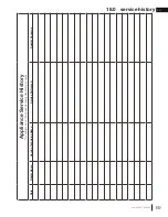
Страница 69: ...08 09 21 69 service history Appliance Service History This appliance must be serviced annually depending on usage Date Dealer Name Service Technician Name Service Performed Special Concerns 18 0 serv...

Страница 70: ...oute Transcanadienne Montr al Qu bec H4T 1A3 24 Napoleon Road Barrie Ontario Canada L4M 0G8 214 Bayview Drive Barrie Ontario Canada L4N 4Y8 103 Miller Drive Crittenden Kentucky USA 41030 Phone 1 866 8...

Страница 71: ...nstall dans une maison pr fabriqu e mobile d j install e demeure si les r glements locaux le permettent Cet appareil doit tre utilis uniquement avec le type de gaz indiqu sur la plaque d homologation...

Страница 72: ...jets doivent tre gard s une distance d au moins 4 pieds 1 22m du devant de l appareil Assurez vous de disposer de mesures de s curit ad quates pour emp cher les jeunes enfants de toucher aux surfaces...

Страница 73: ...n devraient tre effectu es par un technicien qualifi Il est imp ratif que les compartiments de contr le le br leur et les passages de circulation d air soient gard s propres afin de fourni une combust...

Страница 74: ...ire ces instructions avant de faire fonctionner 106 10 2 instruction d allumage 106 11 0 finitions 107 11 1 enl vement du support de transport 107 11 2 retrait de l cran de protection principal et l i...

Страница 75: ...l BHD4STFCPA Berceau de feu Propane Type de carburant Gaz Naturel Propane Altitude pi 0 4 500 D bit maximal BTU h 30 000 Puissance minimum BTU h 23 000 Pression minimale d alimentation en gaz 4 5 w c...

Страница 76: ...r duit au taux de 4 pour chaque 1000 pieds 305mm suppl mentaires Les bruits caus s par l expansion et la contraction lors des cycles de chauffage et de refroidissement sont tout fait normaux et il fa...

Страница 77: ...cas o le soufflerie est quip d un cordon d alimentation il doit tre connect une r ceptacle correctement mise la terre La fiche de mise la terre ne doit pas tre retir du cordon d alimentation Ce qui s...

Страница 78: ...verture de l appareil WARNING Do not add any material to the appliance which will come in contact with the flames other than that supplied by the manufacturer with the appliance AVERTISSEMENT N ajoute...

Страница 79: ...325mm 251 8 638mm 79 16 192mm 79 16 192mm 21 16 53mm 343 16 868mm 45 1143mm 381 4 841mm 79 16 192mm 79 16 192mm 21 16 53mm 8 203mm 5 127mm 251 8 638mm 1213 16 325mm ENTR EDU LECTRIQUE ENTR EDU GAZ EN...

Страница 80: ...Site Web SureSeal Metal Fab 5DNA Wolf Steel www mtlfab com Direct Vent Pro Simpson DuraVent W175 0170 Wolf Steel www duravent com Pro Form BDM N A BDM www dalsinmfg com Direct Temp Selkirk 5DT AAN Se...

Страница 81: ...nt scell s l aide de silicone haute temp rature RTV ou d un ruban d aluminium appropri qui couvre toute la circonf rence de chaque joint dans le syst me de ventilation Cela garantira les meilleures pe...

Страница 82: ...e imm diatement la sortie de l appareil d un minimum de 57 pouces 144 8cm Sur toutes les courses horizontales assurez vous que la pente des conduits d vent ne soit pas descendante Quand elle se termin...

Страница 83: ...eds 2 4m pour un po le 8 2 3 2 installations particuli res d vents 3 2 1 ensemble p riscopique 12 30 5cm au niveau de sol 38 1 4 97 2cm min 24 61cm min ind pendamment de la longueur d vent horizontale...

Страница 84: ...ll Pac pour sceller l int rieur du conduit l adaptateur Utilisez le scellant Mill Pac pour sceller l adaptateur aux colliers de l appareil Utilisez le scellant RTV rouge haute temp rature pour sceller...

Страница 85: ...le tableau pour les dimensions d un mur plus large R 6 1 8m 6 1 8m Voir la tableau pour les dimensions d un mur plus profond La terminaison ne doit pas tre install e sur quelconque mur ayant une ouver...

Страница 86: ...2m La course horizontale la course verticale jusqu un maximum de 40 12 2m Terminaison verticale 11 1 Les symboles suivants sont utilis s dans le calcul et les exemples d vacuation plus grand que plus...

Страница 87: ...iguration de l vacuation exige plus qu un coude de 45 et de 90 les formules suivantes s appliquent Formule 1 HT VT Formule 2 HT VT 40 pieds 12 2m Exemple V1 8 PI 2 4m VT V1 8 PI 2 4m H1 2 5 PI 0 8m H2...

Страница 88: ...2m 5 5 PI 1 7m 19 1 PI 5 8m Formule 1 HT 4 2 VT 4 2 VT 4 2 PI 1 3m x 5 5 PI 1 7m 23 1 PI 7m 13 6 PI 4 2m 23 1 PI 7m Formule 2 HT VT 24 75 PI 7 5m 19 1 PI 5 8m 24 75 PI 7 5m Puisque les deux formules...

Страница 89: ...rmule 2 HT VT 40 pieds 12 2m Exemple V1 5 PI 1 5m V2 10 PI 3 1m VT V1 V2 5 PI 1 5m 10 PI 3 1m 15 PI 4 6m H1 3 PI 0 9m H2 2 5 PI 0 8m HR H1 H2 3 PI 0 9m 2 5 PI 0 8m 5 5 PI 1 7m HO 0 03 un coude 45 troi...

Страница 90: ...35 0 03 45 270 135 5 4 PI 1 6m HT HR HO 8 PI 2 4m 5 4 PI 1 6m 13 4 PI 4 1m HT VT 13 4 PI 4 1m 2 5 PI 0 8m 15 9 PI 4 8m Formule 1 HT 3VT 3VT 3PI 0 9m x 2 5PI 0 8m 7 5PI 2 3m 13 4PI 4 1m 7 5PI 2 3m Puis...

Страница 91: ...nfiltration d isolant souffl Assurez vous que l isolation et les autres mat riaux sont bien fix s Lorsque vous construisez l enceinte pr voyez l paisseur des mat riaux de finition pour maintenir les d...

Страница 92: ...cm B MIN 42 1 2 108cm MAX 43 1 2 110 5cm Toute les dimensions de l ossature sont bas s sur la position du support de finition L ossature peut changer d pendant de l paisseur du mat riaux de finition V...

Страница 93: ...tible mais ne doit pas d passer l ouverture de l appareil Voir la section vacuation COMBUSTIBLE MAT RIAUX INCOMBUSTIBLE BRIQUE 3 76mm 2 51mm COUPE FEU 43 109 2cm PLUS L L VATION 45 114 3cm 6 152mm MIN...

Страница 94: ...composants d vacuation vous devez aussi installer trois vis pour vous assurer que le raccordement ne d fasse pas Ne serrez pas la gaine flexible Risque d incendie d explosion ou d asphyxie Si l ensemb...

Страница 95: ...ntre la trou et fixez l aide des quatre vis fournies dans le sac de votre manuel B Une fois que le conduit d vent est en place appliquez du scellant Mill Pac rouge W573 0002 non fourni entre le condui...

Страница 96: ...tout autour et placez un espaceur coupe feu par dessus le protecteur de conduit d vacuation pour emp cher l arriv e d air froid dans la pi ce ou autour de l appareil Assurez vous que l espaceur coupe...

Страница 97: ...t noir haute temp rature Mill Pac W573 0007 non fourni l exception du raccordement du conduit d vacuation la buse de l appareil qui doit tre scell avec le scellant Mill Pac N utilisez que les ensemble...

Страница 98: ...anche en la scellant avec du calfeutrage non fourni D Si plus de sections de gaine doivent tre utilis es pour atteindre l appareil raccordez les ensemble tel qu illustr Le syst me d vacuation doit tre...

Страница 99: ...toit d au moins 16 40 6cm une fois fix e E Enlevez les clous des bardeaux sur le dessus et les c t s du connecteur de terminaison Placez le solin par dessus le connecteur de terminaison en laissant u...

Страница 100: ...t appareil si une partie quelconque a t submerg e Contactez imm diatement un technicien de service qualifi pour inspecter l appareil pour des dommages au circuit lectrique Risque de chocs lectriques o...

Страница 101: ...rs des quatre vis paulement Sela facilitera l acc s au bo tier de piles C Trouvez la sauvegarde de piles dedans le compartiment de soupape D Installez 2 piles alcalines D non fournies dans la sauvegar...

Страница 102: ...lectrique 110 V AVERTISSEMENT I S 1 4 3 16 3 8 1 2 9 5mm 12 7mm LA FLAMME DOIT ENVELOPPER LA PARTIE SUP RIEURE DE LA SONDE DE FLAMME DE 3 8 9 5mm 1 2 12 7mm LECTRODE LA SONDE DE FLAMME VEILLEUSE FIL V...

Страница 103: ...soupape L alimentation en gaz doit tre d branch e pendant les essais de pression de ce syst me lorsque les pressions d essai exc dent 1 2 LB PO2 3 5 KPA Les r glages de la soupape ont t faits en usine...

Страница 104: ...fixation vous devez d abord calculer l paisseur des mat riaux de fintion p ex panneau de gypse Ceci permettra de calculer les dimensions partir de la face du caisson ext rieur jusqu aux supports de f...

Страница 105: ...eur murale de l appareil la position ON J Si l appareil ne fonctionne pas suivre les instructions de couper l alimentation de gaz et puis appelez votre technicien de service ou fournisseur de gaz A R...

Страница 106: ...AS IS HEAVIER THAN AIR AND WILL SETTLE ON THE FLOOR WHAT TO DO IF YOU SMELL GAS TURN OFF ALL GAS TO THE APPLIANCE OPEN WINDOWS DO NOT TRY TO LIGHT ANY APPLIANCE DO NOT TOUCH ANY ELECTRICAL SWITCH DO N...

Страница 107: ...pas fonctionner l appareil lorsque la porte vitr e est enlev e fissur e bris e ou gratign e Les mat riaux de fa ade ou de finition ne doivent jamais empi ter sur l ouverture de l appareil L assemblage...

Страница 108: ...ig 1 B Tirez l ecran vers l avant et l ext rieur de l appareil Fig 2 FIG 1 FIG 2 11 3 retrait de l cran de protection fin et l installation seulement BHD4P_A Un de les cran principals doit tre enlev e...

Страница 109: ...ber par terre D Quand les loquets sont rel ch s tirez la porte en avant et lors de la support au fond de la porte E Renversez ce processus pour installer la porte LATCHES FIG 1 FIG 2 LOQUETS AVERTISSE...

Страница 110: ...tapes dans l ordre inverse 6 Vis COUVERCLE DU PANNEAU COUVERCLE DU PANNEAU DE CONTR LE 11 6 enl vement de panneau de contr le A Enlevez l ecran de protection voir la section retrait de l cran de prin...

Страница 111: ...utilis entre les carreaux un coulis base de polym re tel que Mapei Ultracolour plus est recommand Appr t Peinture Pour une surface peinte utilisez un appr t au latex 100 acrylique et une couche de fin...

Страница 112: ...1 2 pouces 13mm a t install Desserrez les 8 vis sur chaque support de finitions Ajustez le support de finition la position finale VUE DU C T B A 1 1 2 38mm MAX 1 2 13mm MIN 1 1 2 38mm MAX MIN Dimensio...

Страница 113: ...8 203mm 6 152mm A 10 254mm 8 203mm L A T A B L E T T E H A U T E U R D E PROFONDEUR DE LA TABLETTE Ref Mantel Height Mantel Depth A B C D E 16 406 4mm 14 355 6mm 12 304 8mm 10 254mm 8 203 2mm 6 152 4...

Страница 114: ...m 6 152 4mm 2 50 8mm 5 127mm 3 76 2mm 4 101 6mm 6 152 4mm 2 50 8mm 5 127mm B B A A 4 101 6mm Porte Porte Moulure optionnelle Sommet de l appareil Sommet de l appareil AVERTISSEMENT 44 4 Les mat riaux...

Страница 115: ...ux portes B Placez la base de protection 3 la c t du pilote comme illustr e en Figure B C Placez la base de protection 1A la c t droite et la base de protection 1 la c t gauche de l appareil comme ill...

Страница 116: ...he 2 Fig 2 4 Placez b che 3 sur l pingle en b che 2 il devrait se reposer sur la base de protection la c t droite Fig 3 Placez une pingle dans b che 2 Fig 2 5 Placez b che 4 sur l pingle en b che 2 il...

Страница 117: ...z b che 11 sur l pingle en b che 1 il devrait se reposer sur la base de protection la c t gauche Fig 11 13 Placez la morceau de charbon 12 sur les deux pingles au centre du bruleur Fig 12 14 Installez...

Страница 118: ...br leur Le blocage des orifices du br leur peut cr er une flamme irr guli re des d p ts de carbone et un retard d allumage 22 2 parpillez les braises l avant et sur les c t s du support b ches de fa...

Страница 119: ...itrifi es ni vermiculite sur ou autour de l ouverture de la veilleuse ni sur les orifices du br leur Ceci interf rait avec l op ration de la pilote parpillez soigneusement les braises vitrifi es sur l...

Страница 120: ...W415 4020 08 09 21 120 FR finitions LOGO 1 2 13mm 1 2 13mm 11 13 mise en place du logo...

Страница 121: ...races de peinture ou de surpulv risation enlevez les de l assemblage de la veilleuse ou remplacez le Une toile d meri ou un tampon r curage comme Scotch Brite peut tre utilis pour enlever la peinture...

Страница 122: ...ctions sont incluses avec l ensemble Si l vacuation de cette appareil t r duite 4 7 seulement utiliser une RP4 pour restreindre l vacuation verticale note BR LEUR DE VERRE BR LEUR DE B CHES BR LEUR DU...

Страница 123: ...igne le br leur 5 Si votre appareil est fourni avec une cran de protection le nettoyage peut tre n cessaire en raison d un exc s de poussi re peluches des tapis animaux etc utilisez un l attachement d...

Страница 124: ...bustion Consultez la section pour l enl vement de la porte et retirez la porte comme indiqu Consultez la section pour l enl vement de l cran de protection et retirez la porte comme indiqu Enlevez soig...

Страница 125: ...r installer le br leur renverser ces tapes 38 1 AVERTISSEMENT N utilisez pas de mat riaux de substitution La vitre peut tre chaude ne touchez pas la vitre jusqu ce qu elle ait refroidi Usez de pruden...

Страница 126: ...levez les porte s pour les instruction voir la section installation enl vement de la porte B Soigneusement enlevez les roches ou braises vitrifi es de l appareil C Pour enlever le plateau soulevez l t...

Страница 127: ...fixer l assemblage de la soupape D Soulevez l assemblage de la soupape avec soin suffisamment loin pour acc der la soupape d arr t manuelle puis tournez la OFF D branchez le raccord flexible de la so...

Страница 128: ...les pi ces peuvent tre command es chez votre d taillant autoris Pour un remplacement de pi ce sous garantie une photocopie de la facture originale sera requise afin de pouvoir honorer la demande Lorsq...

Страница 129: ...024 W333 0023 W333 0022 W710 0059 SER W010 3481 W010 2997 W010 3208 SER W707 0002 Transformateur W010 2829 25 17 18 19 20 16 23 21 24 22 W655 0561 SER C t droite Panneau d acc s de la soupape Br leur...

Страница 130: ...n de retenue Oui Br leur pour roches et braises vitrifi es L assemblage de la soupape de br leur pour les b ches Br leur pour braises vitrifi es L assemblage de la soupape de br leur pour braises vitr...

Страница 131: ...r de verre 2 4 3 1 2 4 3 1 R f No de pi ce Description 1 W010 2954 SER Assemblage du br leur 2 W080 1400 SER Support du br leur 3 W290 0018 Joint d tanch it du venturi 4 W720 0005 Venturi Ces articles...

Страница 132: ...de contr le W080 2066 Support de soupape W725 0104 Soupape GN Oui Oui 2 W456 0052 Oui 8 W725 0105 Soupape P Oui W010 3040 Assemblage de veilleuse P 10 Oui Injecteur de veilleuse 52 P GD19 VALVE ASSEM...

Страница 133: ...lage du br leur 2 W080 1463 Support du br leur 3 W290 0018 Joint d tanch it du venturi R f No de pi ce Description 4 W720 0005 Venturi 5 W080 1399 Support du br leur Ces articles peut diff rer de cell...

Страница 134: ...cle d acc s soupape 14 W290 0247 Joint d tanch it Oui 15 W175 0311 Raccord flexible 3 8 W175 0217 Raccord flexible avec soupape W010 3040 Assemblage de veilleuse P 11 Oui Oui GD19 VALVE ASSEMBLY ITEMS...

Страница 135: ...s de verre vari t de couleurs GD851KT PRPHD4 10 3 19 20 21 Oui 9 22 4 MRKM Ensemble mineral rock 8 9 W135 0529 B che 3 W135 0528 B che 2 W135 0527 B che 1 PRPHD4 Panneau r flecteur radiant en porcelai...

Страница 136: ...au savonneuse Le volet d air est r gl incorrectement Voir la section r glage du venturi pour le r glage de l ouverture du volet d air dans le manual d installation Du carbone se d pose sur la vitre le...

Страница 137: ...terre Assurez le bon polarit du thermocouple si fourni V rifiez si les assemblages de le veilleuse et de la soupape sont bien mis la terre R cepteur si quip R initialisez la programme tenir le bouton...

Страница 138: ...ue le r cepteur est dans la position milieu La t l commande ne fonctionne pas V rifiez les pile ainsi que leur orientation fils sont courbe s C blage de la soupape est endommag e Remplacez la soupape...

Страница 139: ...p riodes d humidit la condensation des produits chimiques ou produits d entretien nuisibles ne seront pas la responsabilit de Napol on Durant les dix premi res ann es Napol on remplacera ou r parera l...

Страница 140: ...DE CONFORT 7200 Route Transcanadienne Montr al Qu bec H4T 1A3 24 Napoleon Road Barrie Ontario Canada L4M 0G8 214 Bayview Drive Barrie Ontario Canada L4N 4Y8 103 Miller Drive Crittenden Kentucky USA 41...

Отзывы: