NAPCO iSeeVideo ISV WLHDCAM Скачать руководство пользователя страница 4


⇒ 

Make the connections above and plug in the ISVWAP power adaptor 

⇒ 

Attach the antennas to the camera(s) 

⇒ 

Plug in the camera power adaptor 


There are no other steps required to deploy the cameras through the customer’s network; the cameras will automatically begin 
communicating to the iSeeVideo server system. 


Create the new iSeeVideo account and register the cameras as shown on page 5.  


Secure the iSeeVideo Wireless network  


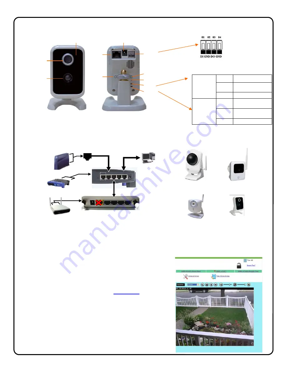
Once all cameras have been registered to the new account and can be viewed, 
the wireless network must be secured. 
 

⇒ 

While viewing each camera, simply click 

Secure Now!

 next to the unlock 

Icon and the camera will send a new, unique 128bit encrypted secure 
key to the Wireless Access Point, providing a secure wireless connec-
tion.  

⇒ 

You will be automatically logged out of the account; log back in to view 
the secured camera to ensure that the unlock icon has change to a 
locked state.  

⇒ 

Repeat for each camera in the system. 

If a new camera is added to the system in the future, simply repeat the above 
procedure to secure it. 

1

 CONFIGURE THE NETWORK CONNECTION  

I

SVWLCA

ISVWLCAMPT 

RESET 

WAN 

4 3  2  1 

POWER 


WAN 

4 3 2 1 

12V/1A 

ISVWAP REAR PORTS (DO NOT USE WAN PORT) 

CUSTOMER'S 

BROADBAND 

CONNECTION 

(MODEM OR 

NETWORK) 

CUSTOMER'S 

ROUTER 

CUSTOMER’S PC  

WAN 

ISVWAP 

ISVWLHDCAM 

Light Sensor                                                 


Lens 

RJ45 for


Ethernet


Reset Button


Privacy


Button


DC Power 


WPS Button (not used)


One D/I and


One D/O


PIR Motion 

Sensor 

Power LED


Network LED


Front View


Rear View


Controls and Indicators 

LED INDICATION TABLE 

POWER 
LED 
  

STEADY  Camera has power


BLINKING 

Camera initializing, trying to 
obtain an IP address


OFF No 

power


NETWORK 
LED 
  

STEADY 

Network connection good, 
not transmitting or receiving


BLINKING 

Camera transmitting or 
receiving data


OFF  No network connection


Input/output        

Terminals  

DI is a N/O input (activates 
upon short of DI to GND)  
 
DO is an open collector output 
that must be connected to a low 
current relay or directly to an 
EOLR terminal on an alarm 
panel zone input. 

ISVWLOCAM 

Содержание iSeeVideo ISV WLHDCAM

Страница 1: ...1701 For Sales and Repairs 800 645 9445 For Technical Service 800 645 9440 Publicly traded on NASDAQ Symbol NSSC NAPCO 2012 Designed exclusively for use with NAPCO iSeeVideo VideoAlert net Server COMP...

Страница 2: ...ed for event triggering Pats Pending PIR Motion Detection Pattern ORDERING INFORMATION ISVWLKIT1 Fixed IP WL Camera Kit 1 ISVWLCAM fixed IP wireless camera mounting bracket Suction Cup Window Bracket...

Страница 3: ...he iSeeVideo portal protected by the default iSeeVideo 128bit encryption Once all cameras are up and running simply click the LOCK icon on the portal to prompt the camera to send a new unique random 1...

Страница 4: ...cked state Repeat for each camera in the system If a new camera is added to the system in the future simply repeat the above procedure to secure it 1 CONFIGURE THE NETWORK CONNECTION ISVWLCAM ISVWLCAM...

Страница 5: ...ll appear Create Subscriber Account Now Click to create a new Subscriber account with this camera and enter the Subscriber details see below ADD or REPLACE a VIP Device To add or replace a camera to t...

Страница 6: ...ation section verifies all information en tered above Be sure to check the accuracy of the information dis played and if changes are required click the Prev button to edit any previously entered infor...

Страница 7: ...Viewer should always be enabled Click Update to add the new user and return to the pre vious screen or click Prev to cancel and return to the previous screen The system supports a maximum of 5 Users i...

Страница 8: ...SC _ _ _ _ _ _ OR 000E8F _ _ _ _ _ _ Click Next 2 The Dealer Branding screen will appear En ter your Company Dealer Admin ID and Password and click Next 3 After Dealer Branding is complete click Add o...

Страница 9: ...continue 5 The following screen allows the en try of the camera description in the Enter New Device Description field Click the pull down menu and se lect Add Device to complete the addition of the ne...

Страница 10: ...live view screen and size it appropriately by pressing SHIFT and dragging a side of the window Once the window is properly positioned and sized the sensitivity threshold can be set by dragging the cor...

Страница 11: ...to activate the microphone on the front of the camera Enable Speaker to activate the speaker line output on the back of the camera HW Trigger Input Select Video Clip to trigger transmission of video c...

Страница 12: ...purporting to act on its behalf to modify to change or to assume for it any other warranty or liability concerning its products In no event shall NAPCO be liable for an amount in excess of NAPCO s or...

Отзывы: