NANOTEC SMCI33 Скачать руководство пользователя страница 12

Technisches Handbuch 

SMCI33 

Connections and circuits 

3.2  Encoder connection: Connector X2 

Optional encoder 

An optional encoder can be connected to the stepper motor control. 

By default, the closed-loop control for a three-channel encoder is set up with 500 
pulses/revolution in an 1.8° stepping motor. With an 0.9° stepper motor, you should 
use an encoder with 1000 pulses/revolution to achieve the same control quality. 
Depending on the application, it may make sense to use higher encoder resolutions 
(up to max. 2000 pulses/revolution) to improve control quality or to use a lower 
resolution (min. 200 pulses/revolution) for low-cost applications or for step monitoring 
alone. 

The following encoder resolutions can normally be processed by the controller: 192, 
200, 256, 400, 500, 512, 1000, 1024, 2000, 2048. 

Recommended: 

Where possible, use Nanotec encoders with the order number 
WEDS/WEDL-5541 Xxx. 

If an encoder is 

not

 used, the "Disable" mode must be set in the "Error correction" tab 

in the "Rotation Direction Mode" selection menu. See the NanoPro separate manual. 

Using encoders with line drivers 

The encoders of the WEDL series with a line driver output an inverted signal in 
addition to the encoder signal; this leads to better interference immunity and is 
especially recommended for long lines lengths. 

We recommend shielding and twisting the encoder line to minimize interference with 
the encoder signal from the outside. To be able to connect negative signals to the 
SMCI33, you require adapter ZK-SMCI-LD. 

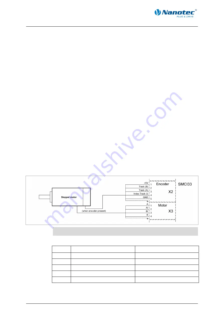
Encoder connection diagram (X2) 


Note:


Complete connection diagram, see Section 2.1. 

Pin assignment connector X2: Encoder 

Pin no. 

Name 

Observations 

1 +5 


2 Track 

(B) 


3 Track 

(A) 


Index track (I) 


5 GND 


12 


Issue: V 2.2 

Содержание SMCI33

Страница 1: ...Technical Manual Stepper motor control SMCI33 NANOTEC ELECTRONIC GmbH Co KG Gewerbestra e 11 D 85652 Landsham near Munich Germany Tel 49 0 89 900 686 0 Fax 49 0 89 900 686 50 info nanotec de...

Страница 2: ...g Germany Tel 49 0 89 900 686 0 Fax 49 0 89 900 686 50 Internet www nanotec de All rights reserved MS Windows 2000 XP Vista 7 are registered trademarks of the Microsoft Corporation Version Change over...

Страница 3: ...It is exclusively intended as a technical description of the product and as commissioning instructions The warranty is exclusively for repair or replacement of defective equipment according to our gen...

Страница 4: ...6 2 2 Commissioning 8 3 Connections and circuits 10 3 1 Inputs and outputs I O Connector X1 10 3 2 Encoder connection Connector X2 12 3 3 Stepper motor connection Connector X3 13 3 4 Voltage supply co...

Страница 5: ...optional encoder RS485 or USB interface for parameterisation and control Sequence programs with NanoJ Network capability up to 254 motors Easy programming with the NanoPro Windows software Closed Loo...

Страница 6: ...ware and significantly reduce commissioning time More detailed information on this can be found in the separate NanoPro user manual Rotation monitoring Even if stepper motors do not lose steps during...

Страница 7: ...Technisches Handbuch SMCI33 Connection and commissioning Connection diagram SMCI33 Issue V 2 2 7...

Страница 8: ...Action Note 1 Install the NanoPro control software on your PC See the NanoPro separate manual Download of www nanotec com 2 Connect the controller to the stepper motor according to the connection dia...

Страница 9: ...m control system hardware 10 Select the 115200 bps entry in the Baudrate selection field 11 Check the current setting using the motor data sheet Under no circumstances may the current be set to a valu...

Страница 10: ...MC 2 4 5 12 Connection diagram Pin assignment Pin no Name Observations 1 Input 1 5 24 V Optocoupler 2 Input 2 5 24 V Optocoupler 3 Input 3 5 24 V Optocoupler 4 Input 4 5 24 V Optocoupler 5 Input 5 5...

Страница 11: ...low NPN with NanoPro Input circuits All inputs apart from the Analogue In input are electrically isolated by optocouplers from the voltage supply of the SMCI33 and designed for 5 24 V input signals a...

Страница 12: ...192 200 256 400 500 512 1000 1024 2000 2048 Recommended Where possible use Nanotec encoders with the order number WEDS WEDL 5541 Xxx If an encoder is not used the Disable mode must be set in the Erro...

Страница 13: ...ed stepper motor Never disconnect the link when operating voltage is applied Never disconnect lines when live Connection diagram Note Complete connection diagram see Section 2 1 Pin assignment connect...

Страница 14: ...ge 50 V will destroy the output stage Mixing up the connections can destroy the output stage Never disconnect the link when operating voltage is applied Never disconnect lines when live Connection dia...

Страница 15: ...tions 1 NC Not assigned 2 Rx RS 485 Rx 3 5 V Output 5 V 4 Tx RS 485 Tx 5 NC 6 NC 7 Rx RS 485 Rx 8 GND Output GND 0 V 9 Tx RS 485 Tx Two wire operation To enable RS485 two wire transmission capability...

Страница 16: ...Technisches Handbuch SMCI33 Connections and circuits Circuit diagram RS485 network 16 Issue V 2 2...

Страница 17: ...internal reference point at the set minimum speed index mark of encoder only in combination with an encoder External reference run During an external reference run the motor travels to a switch conne...

Страница 18: ...ck mode The motor is controlled in this operating mode simply with a potentiometer or a joystick 10 V to 10 V Use this mode if you want to use the motor in a simple application Setting a specific spee...

Страница 19: ...rrect module address See the separate manual on NanoPro The power supply of the SMCI33 is interrupted Check voltage supply switch on if necessary Another open program is blocking the COM port to which...

Страница 20: ...ep Quarter Step Fifth Step Eighth Step Tenth Step 16th Step 32nd Step 64th step Adaptive microstep 1 128 Step frequency 0 to 50 kHz in clock direction mode 0 to 25 kHz in all other modes Position moni...

Страница 21: ...et of datasheets is available for downloading at www nanotec de Connectors The following connectors are available on the SMCI33 Connectors X1 X2 X3 and X4 Phoenix connector type MICRO COMBICON Connect...

Страница 22: ...X3 13 Connector X4 14 Connector X5 15 E Encoder 6 12 Encoder connection diagram 12 I Input circuits 11 Inputs and outputs I O 10 N NanoJ 6 O Operating modes 17 Operating voltage 14 Output circuits 11...

Отзывы: