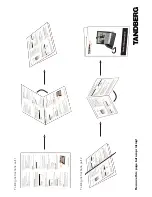
INSTALLATION OF THE COMMUNICA-
TOR REGGAE MINI GT/GTBZ
Location requirements for communicator
REGGAE mini GT
Handle the REGGAE mini GT communicator circuit board
with care to avoid damaging (breaking) ferrite inductors,
particularly on the underside of the circuit board
Fasten the circuit board into the panel box or into other
device with four self-adhesive distance columns (inclu-
ded in the package of REGGAE mini GT communicator)
While placing the circuit board of communicator onto
metal underlay, secure the space underneath the bottom
side Check, if any surface inequalities are not too close
to the board components Minimum distance between
components and surface must be more than 2 mm
Placement requirements for communicator
REGGAE mini GTbz
In the rear wall of the metal box of communicator
REGGAE mini GTbz are prepared holes for stretching
all the cabling Holes are blanked off from production
Remove blanking metal wheels from needed holes and
stretch the cabling into the box of communicator
Fasten the box of communicator on the wall using three
screws, there are three holes designate on rare wall of the
metal box Two holes are adapted for hanging up in the
upper corners of the box Into the third hole in the mid-
dle of the bottom part of the box screw a screw, which
will fix the box against slipping out of hanging
After installing the metal box on the wall, always check
the strength of gripping to prevent later injury or
damaging estate by releasing the communicator box
from hanging!
Connecting the GSM/GPRS antenna
GSM/GPRS antenna must be placed outside the metal
box, where the communicator is placed, otherwise
proper communication will not be ensured
High frequency output emitted by an antenna may cause
interferences to nearby mechanisms that are sensitive
to high frequency fields and if the antenna is badly pla-
ced, this may cause the disruption of the circuit of the
communicator itself If disruptions occur on the telepho-
ne line or on other parts of the connected mechanism,
either change the type of antenna used or place the
antenna further away from the interference mechanism
Coaxial antenna cable designed for interior is thin and
flexible Such antenna types are possible to connect
without major problems directly to the SMA connector of
the communicator Always make sure to avoid breakage
of the coaxial cable, or a sharp bend on a small radius
It is most common to use thin rod antenna for bands
GSM 900/1800, screwed directly on the SMA connector
of the REGGAE mini GTbz communicator
It is appropriate to connect external antenna and com-
municator with quality coaxial cable (impedance 50 Ω),
e g type RLH1000 Such cable type cannot be direct-
ly connected to SMA connector of the communicator
To connect inflexible coaxial cable to connector of the
communicator use short flexible cable reduction with
corresponding connectors (e g SMA <--> N)
Connecting the inputs
Connect the insulated voltage inputs and uninsulated in-
put In the inputs description and in the communicator
configuration you will find detailed information about
inputs function
Connecting the output
Connect the relay output In the relay outputs descripti-
on and in the communicator configuration you will find
detailed information about technical parameters and
about outputs function
Connecting the telephone line
Connect the panel ESS telephone line RING/TIP onto ter-
minal plates marked as “R1” and “T1” of the communica-
tor REGGAE mini GT circuit board
Detailed information about technical parameters and
about functions of telephone communication can be
found in description of the telephone section of commu-
nicator and in description of communicator configuration
In case of problems during communication of the ESS
panel with the circuit board of the REGGAE mini GT com-
municator, monitor the telephone line in order to remove
the defects
U
S
E
R
M
A
N
U
A
L
www.namsystem.com
REGGAE mini GT/GTbz
Communicator for GPRS transmission
12