background image

2. Starting up

3. Maintenance

4. Transport and storage

Before starting up the device,make sure that:

1.  The apparatus is well secured and the electrical connections have been carried out correctly.

2.  The safety devices have been adequately connected.

3.  No loose material or fitting remains that can be sucked up by the ventilator. If the ventilator has been 

mounted in a duct, make sure it is clear of loose material.

4.  The earth fittings are adequately connected.

5.  The electrical safety devices are correctly connected, adjusted and ready for use.

6.  The wire and electrical connections inputs are correctly sealed and water-tight.

When starting up the machine, make sure that:

1.  The propeller turns in the correct direction.

2.  There are no abnormal vibrations.

3.  If any of the electrical safety devices blow, the apparatus must be quickly disconnected from the mains 

supply. The whole installation should be carefully checked before trying to start up the machine again.

1.  Before  manipulating  the  ventilator,  make  sure  it  is  disconnected  from  the  mains  supply  even  if  it  has 

previously  been  switched  off.  Prevent  the  possibility  of  anyone  else  connecting  it  while  it  is  being 

manipulated.

2.  The  apparatus  must  be  regularly  inspected.  These  inspections  should  be  carried  out  bearing  in  mind 

the machine’s working conditions, in order to avoid dirt or dust accumulating on the propeller, turbine, 

motor or grids. This could be dangerous and perceptible shorten the working life of the ventilator unit.

3.  While cleaning, great care should be taken not to unstable the propeller or turbine.

4.  All maintenance and repair work should be carried out in strict compliance with each country’s current 

safety regulations.

1.  The packaging user for this apparatus has been designed to support normal transporting conditions. The 

apparatus must always be transported in its original packaging as not doing so could deform or damage 

the product.

2.  The product should be stored in a dry place in its original packaging, protected from dust and dirt until 

it is installed in its final location. Do not accept delivery if the apparatus is not in its original packaging or 

shows clear signs of having been manipulated in any way.

3.  Do not place heavy weights on the packed product and avoid knocking or dropping it.

11

ALNOR

®


ventilation systems

is a legally protected trademark and technical patent. All rights reserved.

w

w

w

.al

nor

.com.
pl

User’s manual

DV-PP-L

Содержание DV-PP-L Series

Страница 1: ...Wentylator kana owy DV PP L INSTRUKCJA OBS UGI USER S MANUAL Sierpie 2019 r Duct fan DV PP L Model DV PP L 100 DV PP L 125 DV PP L 150...

Страница 2: ...w i u ytkownika 3 1 2 Bezpiecze stwo w trakcie monta u 3 2 Uruchomienie 4 3 Konserwacja 4 4 Transport i przechowywanie 4 5 Monta i demonta 5 6 Pod czenie elektryczne 6 6 1 Diagram pod czenia 6 6 2 Dia...

Страница 3: ...uj ce standardy Standard zgodny z Dyrektyw niskonapi ciow 2006 95 WE Standardy kompatybilno ci elektromagnetycznej zgodne z dyrektyw 2004 108 WE 4 Wentylatory lub urz dzenia je obejmuj ce zosta y zapr...

Страница 4: ...cji przy urz dzeniu prosz si upewni e jest ono od czone od zasilania nawet je eli zosta o wcze niej wy czone Prosz dopilnowa aby nikt nie mia mo liwo ci ponownego pod czenia urz dzenia do zasilania w...

Страница 5: ...5 Monta i demonta 1 Zdejmij klamr zaciskow 1 Zdejmij zacisk rubowy 2 Przymocuj baz 3 Zamontuj korpus silnika Dla modeli DV PP L 100 DV PP L 125 Wyj tkowy projekt wspornika pozwala na to aby centralny...

Страница 6: ...nym Ma e wymiary gabarytowe wentylator w DV PP L u atwiaj monta w trudno dost pnych miejscach gdzie przestrze jest ograniczona 6 Po czenie elektryczne br zowy br zowy br zowy br zowy niebieski niebies...

Страница 7: ...ia y LB LA N N MOC N KOMUN LB MA A PR DKO LA DU A PR DKO C PRZE CZNIK L 15min 20min 25min 30min 7 5min 5min 10min 5min P 30min A1 N A2 E A1 N A2 15min 20min 25min 30min 7 5min 5min 10min 5min P 30min...

Страница 8: ...szego punktu zbieraj cego tego typu odpady W razie pyta na temat produkt w prosz skontaktowa si z naszym serwisem posprzeda owym lub z miejscowym sprzedawc 8 Klasy energetyczne E 2018 1254 2014 33 dB...

Страница 9: ...13 6 1 Wiring diagram 13 6 2 Wiring diagram with a speed controller 13 6 3 Wiring diagram with a switch control 14 6 4 Wiring diagram for the model with delay timer switch 14 6 4 1 Speed setting 14 6...

Страница 10: ...tic Compatibility 2004 108 CEE 4 Ventilators or apparatus that include them have been designed to move the air in the area stipulated on their characteristics plate 5 This apparatus must not be used i...

Страница 11: ...bility of anyone else connecting it while it is being manipulated 2 The apparatus must be regularly inspected These inspections should be carried out bearing in mind the machine s working conditions i...

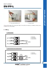
Страница 12: ...odels The unique design of the support bracket allows the central cartridge holding the motor and impeller as sembly to be fitted or removed without dismantling the ductwork For DV PP L 150 model ALNO...

Страница 13: ...s 6 Wiring brown brown brown brown speed controller blue blue black black white white N LB LA N LA LB N N POWER POWER N COMMUN LB LOW SPEED LA HIGH SPEED N COMMUN LA HIGH SPEED L L 6 1 Wiring diagram...

Страница 14: ...15min 20min 25min 30min 7 5min 5min 10min 5min P 30min A1 N A2 E A1 N A2 PLUG SV brown brown black black white blue L LT N COM MH ML POWER MOTOR HIGH HIGH LOW LOW RUN ON TIMER SPEED SETTING 5min 30mi...

Страница 15: ...our after sales service oryour local dealer 8 Energy classes E 2018 1254 2014 33 dB ENERGIA ENERGIJA ENERGY ENERGIE ENERGI A A 530 m3 h DV PP L 150 Model Noise level dB Air flow m3 h Energy class DV P...

Страница 16: ...ut prior notification PRODUCENT zastrzega sobie prawo do wprowadzenia wszelkich ulepsze technologicznych lub modyfikacji bez wcze niejszego powiadomienia ALNOR ventilation systems is a legally protect...

Отзывы: