Nakanishi E3000C Скачать руководство пользователя страница 4

(1) Control Unit

5

6

SPECIFICATIONS

(1)  The E3000 system is designed to be mounted in a CNC lathe, robot, NC lathe or special

purpose machine for drilling, milling, slitting, grinding or other similar application.

(2)  A high-speed brushless motor is used to achieve a maximum speed of 60,000 min

-1

and

eliminate the nuisance of brush maintenance.

(3)  Speed control and protection functions utilize a high performance microprocessor.
(4)  Automatic control and monitoring of spindle functions are possible.
(5)  Wide speed range, 1,000-60,000 min

-1

makes high precision machining possible.

(6)  Compact control unit design allows easy installation in space restricted machines.

Connectors and control panel are front mounted for easy access.

(7)  Control Unit is capable of being connected to AC100V to 240V power sources.
(8)  Two types of control units are available. Standard type NE211 and NE211-OP1 which

conforms to European standards for safe, automatic machine operation.

(9)  Gear Mode Select Switch installed. Set Gear Mode to display the rotating speed at the

cutting tool when using an angle spindle or speed reducer.

(10) The motor/spindle housing is made of Stainless Steel (SUS-416), precision ground to 20,

25 or 30mm making the motor/spindle very versatile and easy to mount on NC or special
purpose machines.

(11) Installation and motor replacement for the E3000 system is very simple because the

connector is placed at the rear of the motor.

*

Note2 <NE211-OP1 Features>

• 

The installed Safety Relay is designed to comply with EN standards, ‘a’ contacts switch the Motor Power Line
and ‘b’ contacts switch the external outputs to the machining center’s controller.

• 

The Safety Relay utilizes Normally Open contacts. The Emergency Stop Signal lines must be supplied with
power to hold the Safety Relay contacts closed and allow the control unit to supply power to the motor. Any
system errors, trouble with the machining center or the connections between the E3000 control unit and the
machining center’s controller will cause the relay contacts to open and the E3000 motor to stop.

• 

The Emergency Stop Signal Input can be connected to any and all portions of the machine’s safety systems to
stop the E3000 motor any time that stoppage of the spindle and motor is required.

• 

The ‘b’ contact outputs can be used to detect an open circuit on the motor line and integrated with the
machines safety systems to stop the machine in case of trouble. If the ‘a’ contacts of the Safety Relay are
welded together by an over load or short circuit the ‘b’ contacts’ separation is maintained at more than 0.5mm
spacing by the relay’s spring release mechanism.
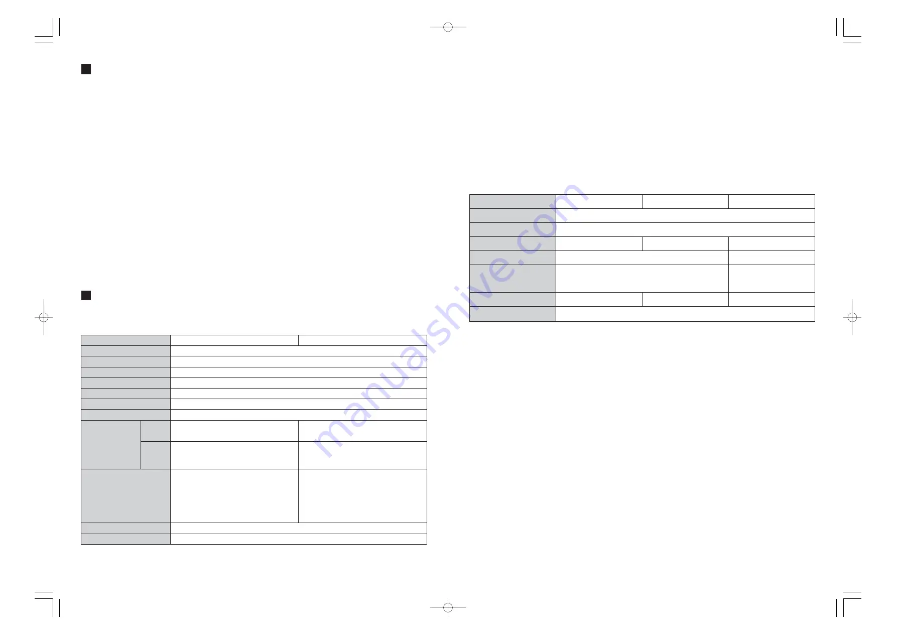
3-1 Specifications

*

Note1 : 

Protectively Separated

FEATURES

(2) Motor Spindle

*

Note :

Collet Chucks are sold separately. Please specify the desired Collet Chuck size when ordering.
CHA-[][] : ø0.5mm-ø4.0mm in 0.1mm increments and ø2.35mm, ø3.175mm
CHK-[][] : ø0.5mm-ø6.0mm in 0.1mm increments and ø2.35mm, ø3.175mm, ø6.35mm

*

Caution! :

Control Limitation of Motor Speed

The fllowing motor is automatically controlled the speed.
So,please check the specification of the Motor Spindle prior to use.
For EM25N-5000,EM25-5000 : 1,000-50,000min

-1

For EM-3030J

: 1,000-32,000min

-1

2

3

Model

NE211

NE211-OP1 

*

Note2

Input

AC100V-240V, 50/60Hz, 1PHASE, 1.8A

Output

AC33V, 0-1KHz, 3PHASE, 2.4A

Operating Temperature

0-40°C

Ambient Humidity

MAX. 85%

Over Voltage Category

Pollution Degree

2

Speed Range

1,000-60,000 min

-1

Control Signal

Input

*

Note1

Transistor Activation Connections : 6
Analog Connections : 1

Transistor Activation Connections : 9
Analog Connections : 1

Output

*

Note1

Transistor Activation Connections : 9
Analog Output Connections : 3

Transistor Activation Connections : 9
Relay Contact Connections : 2 
Analog Output Connections : 3

Protection Circuits

Over-Voltage, Over-Current,
Over Load, Sensor Malfunction,
Overheat, Brake Malfunction,
Spindle Lock, Low Air Pressure,
Start-Up Error, Over-Speed

Over-Voltage, Over-Current, 
Over Load, Sensor Malfunction,
Overheat, Spindle Lock,
Brake Malfunction, Low Air Pressure,
Start-Up Error, Over-Speed, 
Emergency Stop Circuit

Weight

2.8kg

Dimensions

W88 x D138 x H238 mm

Model

EM20-S6000

EM25-S6000

EM30-S6000

Speed Range

60,000 min

-1

Spindle Accuracy

Within 1µm

Diameter

ø20 mm

ø25 mm

ø30 mm

Max. Output

250W

350W

Collet Chuck
(Optional)   

*

Note

CHA-[][]

CHK-[][]

Weight (W/O Motor Cord)

230g

375g

575g

IP Rating

IP64 (If not using cooling air rating is IP40)

E3000C̲K0446E̲e̲080108    08.1.8    6:34  PM    ページ5

Содержание E3000C

Страница 1: ...NECTION P 17 CHANGING CUTTING TOOLS P 18 REPLACING THE COLLET P 19 FIXTURING THE MOTOR SPINDLE P 19 OPERATION PROCEDURES P 21 EXTERNAL INPUT OUTPUT CONTROL SIGNAL SPECIFICATIONS P 23 PROTECT FUNCTION P 30 BREAK IN PROCEDURE P 32 CUTTING TOOL CAUTIONS P 33 TROUBLE SHOOTING P 34 SYSTEM CHART P 35 SETTING OF OPERATING PARAMETERS P 36 CONTENTS 5 4 3 2 1 6 7 8 9 10 11 12 13 14 15 16 17 18 19 20 21 22 0...

Страница 2: ...xt heavier gage The smaller the gage number the heavier the cord Minimum gage for cord Ampere Rating Volts Total length of cord 120V 240V More Than Not More Than Only the applicable parts of the Table need to be included For instance a 120 volt product need include the 240 volt heading IMPORTANT INSTRUCTIONS AND WARNING Electric Devices 0 6 10 12 6 10 12 16 18 18 16 14 16 16 16 12 16 14 14 14 12 1...

Страница 3: ...le speed 9 Do not use bent broken chipped out of round or sub standard tools They can shatter or explode and may cause injury CAUTION 1 Motor cooling and Spindle purge air is required to operate the system Air hose must be connected to the Air in joint on the front of the control unit Between 0 25MPa 0 3MPa air must be supplied 2 Do not disassemble modify or attempt to repair the unit or motor as ...

Страница 4: ...e connected to any and all portions of the machine s safety systems to stop the E3000 motor any time that stoppage of the spindle and motor is required The b contact outputs can be used to detect an open circuit on the motor line and integrated with the machines safety systems to stop the machine in case of trouble If the a contacts of the Safety Relay are welded together by an over load or short ...

Страница 5: ...lief Screw Rubber Pad Fuse T6 3AL 2pcs Operation Manual 3 3 Standard Equipment 1 NE211 Model Standard Equipment Accessories EM20 S6000 Chuck Nut CHN A Provided Spanner 8 x 5 9 x 11 1pc each Operation Manual 2 EM20 S6000 Sold separately Model Standard Equipment Accessories EM25 S6000 3 EM25 S6000 Sold separately Model Standard Equipment Accessories EM30 S6000 Chuck Nut K 265 Provided Spanner 12 x 1...

Страница 6: ...us Duty Area The following tables express the E3000 milling drilling capacity with the max usable cutting tool diameter under our conditions Cutting tool capabilities vary depending on the tools being used or cutting conditions ø Tool Size S Spindle Motor Speed min 1 F Feed Rate mm min ø Tool Size S Spindle Motor Speed min 1 f Drilling Step mm rev 4 5 S50C Carbon Steel SUS304 Stainless Steel A2017...

Страница 7: ...ellow and 1 Red Continuous operation is possible with up to all 3 green LED s lit If one of the yellow LED s is lit the motor spindle can only be run for a short time Please refer to PROTECT FUNCTION of this manual for allowable duration of high load operation When any of the yellow or red LED s are lit the warning LED Warning 20 will flash if this condition is continued beyond the allowable inter...

Страница 8: ... condition has been detected When a hazardous condition is detected the warning LED blinks and the Digital Speed Indicator 11 alternates between the warning code and the actual or preset speed depending on whether or not the motor spindle is rotating 21 Rotating LED RUN When the motor is rotating this LED will flash 1 Push on the clips on the top and bottom of the fuse holder and remove the fuse h...

Страница 9: ...l unit horizontally the Rubber Pad Provided is installed at the side of the air vents Install the control unit so the air vents are underneath the control unit When installing horizontally remove the 4 screws on the Control Panel and remount the panel at a 90 Angle Before removing the control panel be sure the Power Switch is OFF and remove the Power Inlet Cord 8 4 Proper Clearance When installing...

Страница 10: ...d of the provided ø3 2mm cooling air hose into the back of the motor 3 Insert the other end of the ø4mm cooling air hose into the air output joint 8 on the front of the control unit using the provided ø6mm to ø4mm adaptor 4 Regulate air pressure between 0 25 0 3MPa The system can be set to operate without cooling air Please see parameter setting to set this option Maximum speed is 30 000min 1 when...

Страница 11: ...eft to the designer of the equipment in which NAKANISHI s spindle is installed NAKANISHI offers spindles with a wide variety of capabilities and specifications Please carefully check the product s specifications against the requirements of your application and verify suitability and safety prior to initial use WARNING When installing a motor spindle to a fixed base make sure the fixed base is grou...

Страница 12: ...or A 3 Except setting gear ratio 13 14 17 15 OPERATION PROCEDURES 1 Select Control Mode Manual Auto Fig 26 2 Setting motor rotating direction gear ratio GEAR Motor Start Stop Motor Speed 2 1 Setting Manual Mode 1 Set motor rotating direction Push the motor rotating direction switch 15 Select FWD Right hand rotation Select REV Left hand rotation 2 Set 500 min 1 centering rotation To select 0 5 500 ...

Страница 13: ... Motor Start Command Signal Method Air Input monitoring override Confirmation of Parameter Settings If an error occurs an error signal is output to the Input Output Connectors The default setting is ON Closed and OFF Open this setting can be reversed if desired Please refer to the Setting of Parameters section of this manual for details on reversing these signals 3 Setting other Motor Speed Parame...

Страница 14: ...ignal Table 1 Motor Selection Signal is effective when using Selector Unit NE212 Pin1 COM connected to 24V DC Pin1 COM connected to 0V DC Input Signal There are 8 kinds of input signals rotation command rotation direction error release speed up down signal speed command pulse signal motor selection signal 0 motor selection signal 1 500 min 1 speed command These signals are 24VDC signals from an ex...

Страница 15: ...Stop Signal OFF Open Continuity OFF Open between PIN2 and PIN10 the motor is connected PIN3 and PIN11 continuity ON Closed Safety Relay is OFF PIN4 and PIN12 continuity ON Closed Safety Relay is OFF Auto Mode Operation ON Closed ON Closed Main Power Supply is connected OFF Open Main Power Supply is disconnected Auto Mode Operation PIN5 and PIN13 ON Closed External Power Source input for Emergency ...

Страница 16: ...fety Relay Signal PIN No 3 11 4 12 The Safety Relay will be ON or OFF depending on the state of the Emergency Stop Signal PIN1 9 When there is continuity between PIN3 SAFE 1A and PIN11 SAFE 1B or between PIN4 SAFE 2A and PIN12 SAFE 2B the motor is off If there is no continuity between these pairs of pins then the system is operating normally If the Emergency Stop Signal is OFF Open the Safety Rela...

Страница 17: ... C stop for at least 20 minutes check installation and restart Break In procedure Spindle Housing no hotter than 20 C If hotter than 20 C stop for at least 20 minutes check installation and restart Break In procedure Spindle Housing less than 20 C BREAK IN PROCEDURE Table 4 Steps 3 Resetting System after Error Codes There are 2 methods of releasing error codes 1 Push Error Reset Switch 18 RESET on...

Страница 18: ...er Switch is set to Auto but trying to start with the Start Switch on the Control Panel Motor Cord is connected to the wrong Motor Connector on NE212 Emergency Stop Signal on Input Output Connector B is OFF Open NE211 OP1 Only Error Code Indicated Low Air Pressure Motor Fixed Speed is set in the or parameters Set Gear Mode except 1 0 Foreign Particles stuck in the collet chuck or spindle Collet Nu...

Страница 19: ...type of external signal for motor start method Allows selection of Start signal and Direction Signal or REV Start and FWD Start signals Air Input monitoring override The system can be configured to operate without cooling air maximum speed is 30 000 min 1 Check operating parameter settings CAUTION Once a parameters default setting has been changed the setting will be maintained even if power is di...

Страница 20: ...e parameter being set 7 If you desire to set other parameters push the Motor Speed Adjustment Switch to select the parameter to be set 8 If you are finished setting parameters turn the Power Switch off 37 38 2 3 2 Entering Parameter Setting Mode 3 Setting Procedure While pushing and holding the Error Reset Switch 18 turn the Power Switch 9 On Hold the Reset Switch down for 3 seconds the buzzer wil...

Страница 21: ... be set 7 If you are finished setting parameters turn the Power Switch off 6 Setting Maximum Motor Speed Allows the maximum motor speed to be set Fixes the motor speed in both MANUAL and AUTO modes Procedure 1 Push the Start Switch 2 is displayed This indicates that the Maximum Motor Speed cannot be set 3 Push the Start Switch 4 is displayed This indicates that the Maximum Motor Speed can be set 5...

Страница 22: ...h the Start Switch 2 Display oscillates between and the setting for or 3 Push the Start Switch 4 Display and oscillates between and the setting for or 5 Push the Start Switch 6 Display oscillates between and the setting for or setting motor speed For example display 30 for 30 000 min 1 7 Push the Start Switch 8 Display oscillates between and the setting for or Max motor speed 9 Push the Start Swit...

Отзывы: