


Appendix2 3D Parts
APP2-24
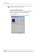
Notes on Usage
•
If the [~\GVW\Parts\User] folder in the computer you are going to operate for
screen editing does not store a bitmap used in the screen data, the bitmap
file is automatically created at the time of opening the screen data and is
registered in the folder. If another bitmap file having the same name already
exits, the above-mentioned automatic file creation is not executed. Use the
[Refer] button in the [Customize] tab window and execute reading of the
bitmap file again. A bitmap file registered by automatic creation is not
completely identical to the original file.
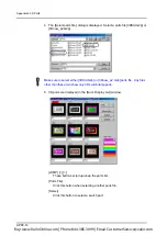
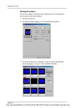
•
Switches and lamps are drawn in the REP mode.
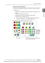
•
Transparent color
The GV series recognizes areas on a screen colored black (code 0000) as
transparent. When there is an area that should not be depicted on the
screen, color it black. To depict black areas instead of transparent areas,
draw them using a color code similar to black.
Buy: www.ValinOnline.com | Phone 844-385-3099 | Email: [email protected]
Содержание GV42C
Страница 2: ...Buy www ValinOnline com Phone 844 385 3099 Email CustomerService valin com...
Страница 4: ...Buy www ValinOnline com Phone 844 385 3099 Email CustomerService valin com...
Страница 12: ...Buy www ValinOnline com Phone 844 385 3099 Email CustomerService valin com...
Страница 20: ...Buy www ValinOnline com Phone 844 385 3099 Email CustomerService valin com...
Страница 22: ...Buy www ValinOnline com Phone 844 385 3099 Email CustomerService valin com...
Страница 132: ...Chapter 2 Screens 2 64 Buy www ValinOnline com Phone 844 385 3099 Email CustomerService valin com...
Страница 134: ...Buy www ValinOnline com Phone 844 385 3099 Email CustomerService valin com...
Страница 264: ...Buy www ValinOnline com Phone 844 385 3099 Email CustomerService valin com...
Страница 272: ...Chapter 5 Transfer 5 8 Buy www ValinOnline com Phone 844 385 3099 Email CustomerService valin com...
Страница 302: ...Buy www ValinOnline com Phone 844 385 3099 Email CustomerService valin com...
Страница 316: ...Buy www ValinOnline com Phone 844 385 3099 Email CustomerService valin com...
Страница 362: ...Buy www ValinOnline com Phone 844 385 3099 Email CustomerService valin com...
Страница 394: ...Buy www ValinOnline com Phone 844 385 3099 Email CustomerService valin com...
Страница 414: ...Buy www ValinOnline com Phone 844 385 3099 Email CustomerService valin com...
Страница 430: ...Buy www ValinOnline com Phone 844 385 3099 Email CustomerService valin com...
Страница 456: ...Appendix2 3D Parts APP2 26 Buy www ValinOnline com Phone 844 385 3099 Email CustomerService valin com...
Страница 458: ...Buy www ValinOnline com Phone 844 385 3099 Email CustomerService valin com...