background image

18

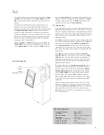
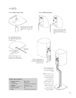
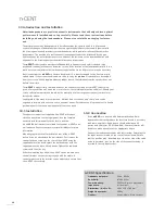
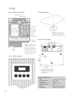
11.8 Floor Protectors

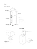
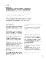
11.6 n-SUB Connection Panel

mains 

input

speaker 
level inputs

RC5 in

RC5 out

Ch 1 left in

Ch 2 right in

mono in

mono out

earth switch

external earth

data RS232 in/out

Note:

 The RS232 sockets 

enable connection to custom 
install RS232 controllers. 
Please contact your dealer for 
the appropriate connection 
cables. These sockets are not 
intended for direct connection 
to computer networks.

n-SUB Specification

Inputs

2 x line level, 1 x speaker level

Frequency Response:


20Hz - 250Hz 

Power Output:


350 Watts

Dimensions (H x W x D):


385 x 385 x 393mm

Weight (unpacked):

29.6kg

Finishes:

Cherry, Maple, Black Lacquer

Mains Supply:


100-120V or 220-240V, 50/60Hz

Naim Floor Protectors can be 
used to if the n-SUB is to be 
installed on a non-carpeted floor.

n-SUB

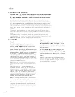
11.7 n-SUB Control Panel

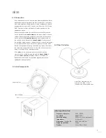
11.9 n-SUB Cable Clamp

25mm
from side

180mm

from 

back

193mm

from side

Fit the supplied Cable Clamp as 
appropriate in one of the three 
positions shown by the cross-
hatched squares .

Содержание ALLAE - 2

Страница 1: ...WO RLD CL AS S H I F I WORLD CLAS S H I F I O W N E R S M A N U A L Speakers SL2 all Ariva axent axess n SATS n CENT n SUB...

Страница 2: ...imits for a class B digital device pursuant to Part 15 of the FCC Rules These limits are designed to provide reasonable protection against harmful interference in a residential installation This equip...

Страница 3: ...this responsibility in any way Introduction Naim Audio products are conceived with performance as the top priority Careful installation will help ensure that their full potential is achieved This man...

Страница 4: ...ical Susceptibility to radio frequency interference is related to the wide internal bandwidth necessary for high sound quality Systems incorporating moving coil phono preamplifiers and active crossove...

Страница 5: ...ling and Installing SL2 Stage 1 With each Lower Cabinet upside down the floor spikes can be fitted Screw a spike and lock nut into each threaded hole in the plinth If the loudspeakers are to stand on...

Страница 6: ...pension Assembly Passive Crossover Unit Tweeter Mounting Points 5 3 SL2 Components Note The metal bar across the rear underside of the SL2 that attaches the Lower Cabinet to the Plinth is intended to...

Страница 7: ...uld be dressed such that they do not touch any other SL2 component and such that the output plugs align naturally with input sockets Stress in the cables will interfere with the decoupling between SL2...

Страница 8: ...are to stand on thinly carpeted or plain floor the spike length should be reduced In either case best results will be achieved when the spike length is set to the minimum required for the spike lock n...

Страница 9: ...ack of the Lower Cabinets to the input sockets on each cabinet Each longer cable should be connected to the sockets on the back of the Upper Cabinets and each shorter cable to the sockets on the back...

Страница 10: ...duce the best results and is necessary with some amplifiers Cable lengths to both loudspeakers should be equal and be between 3 5 metres and 20 metres 11 5ft and 66ft Your local retailer will be able...

Страница 11: ...herry Maple Black 7 3 Plinth Installation location dome location dome floor spike floor spike adjustment access 7 4 Cabinet to Plinth Assembly Lower the cabinet on to the plinth Plinth and cabinet to...

Страница 12: ...dspeaker will be influenced by the room in which it is located and even small changes of loudspeaker position can significantly influence the sound Alignment with the listening position and proximity...

Страница 13: ...B 1W 1m Power Handling 150 Watts music programme Impedance 6 nominal Dimensions H x W x D 175 x 940 x 440mm Weight unpacked 27 4kg Finishes Cherry Maple Black axess Specification Frequency Response 45...

Страница 14: ...3ft clear of room corners and where each loudspeaker is between 5cm and 60cm 2 and 24 away from a solid back wall It is not necessary to angle the loudspeakers inwards towards the listening position T...

Страница 15: ...d using the four small cap head screws and the supplied allen screws and the supplied allen key 9 4 n STAND Installation Remove the two button head Remove the two button head screws and replace them w...

Страница 16: ...full power signals and is intended to be positioned centrally just above or below the screen If the location of the loudspeaker results in too much bass some adjustment of low frequency equalisation v...

Страница 17: ...affected Should a display suffer picture distortion caused by the proximity of the n SUB contact your dealer or installer for advice The n SUB amplifier is cooled by air flow entering through perforat...

Страница 18: ...cess to gain and display control To select and adjust a parameter use the handset mode5or mode6 keys control panel mode to select Once a parameter is selected use the handset up or down keys control p...

Страница 19: ...tening and experimentation if optimum subjective performance is to be achieved Try to put yourself in the position of the film sound designer or music mix engineer and aim for a sound that is consiste...

Страница 20: ...tion to computer networks n SUB Specification Inputs 2 x line level 1 x speaker level Frequency Response 20Hz 250Hz Power Output 350 Watts Dimensions H x W x D 385 x 385 x 393mm Weight unpacked 29 6kg...

Страница 21: ...2 2001 Limits for harmonic current emissions equipment input currents up to and including 16 A per phase Immunity Tested to EN55020 Electromagnetic immunity of broadcast receivers and associated equip...

Страница 22: ...Naim Audio Limited Southampton Road Salisbury England SP1 2LN Telephone 44 0 1722 332266 Fax 44 0 1722 412034 www naim audio com Part No OWMSP 12 001 0033 Drawing No NA401001 400 2...

Отзывы: