16
n-SUB
Note:
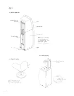
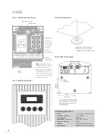
A special 4-pin DIN to stereo RCA Phono Plug lead is required
for connection to Naim preamplifiers (usually via the preamplifier
power supply). It incorporates resistors in the signal path to
protect the preamplifier from the high capacitance inherent in the
necessarily long lead.
Connect to the speaker level inputs using Naim speaker plugs
via cables connected to the main (front left and right) speaker
terminals. The stereo channels are combined to mono within
the
n-SUB.
Speaker terminal “piggy-back” connectors and
appropriate made-up cables will be available from your local
Naim dealer or distributor.
USE OF THE SPEAKER LEVEL INPUTS WITH A NAIM NAP 500,
OR ANY OTHER “BRIDGED” POWER AMPLIFIER, REQUIRES
SPECIAL CONNECTION CABLES. CONTACT YOUR DEALER OR
LOCAL DISTRIBUTOR FOR MORE INFORMATION.
Note:
The decision to use either the line level or speaker level
inputs when the n-SUB is not connected via an AV decoder can be
made on the grounds of sound quality. It is impossible to predict
which option will sound best in a particular system and installation,
however the speaker level option, by virtue of higher signal levels
being more robust over long lead lengths, is potentially superior.
Input sockets can be selected either directly from the
n-SUB
control panel or included in a setup preset. See Section 11.3.
An RC5 control input is also provided on the
n-SUB
connection
panel. This input can be used for wired remote control if the
n-SUB
is to be used out of line-of-sight in an installed audio
system or if the n-SUB is one of a daisy-chained group.
11.2.2 n-SUB Outputs
The
n-SUB
is fitted with a mono signal output and an RC5
control output, both on RCA Phono sockets. These output
sockets are intended to enable “daisy-chaining” of one or more
n-SUBs
in systems where multiple sub-woofers are required.
If these sockets are used take care to ensure that they are
connected correctly.
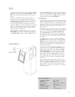
11.2.3 Earth Terminal
An external earth (ground) terminal and earth selection switch
are fitted to the underside of the
n-SUB
. Use of the earth
terminal may help alleviate audible hum from earth loops by
disconnecting the signal and mains earths. If hum is a problem,
connect the earth terminal with a single cable to the preamplifier
earth terminal and move the switch to the “External” position.
Note:
Do not switch the earth selection to External without an
external earth connected.
11.3 n-SUB Configuration and Operation
With all input and output connections made and the
n-SUB
positioned appropriately it is ready for configuration and
operation.
Note:
The n-SUB may be configured and operated from either its
control panel or from the remote handset, however the handset
provides enhanced functionality and direct access to gain and
display control.
To select and adjust a parameter use the handset
mode
5
or
mode
6
keys (control panel:
mode
) to select. Once a parameter
is selected use the handset
up
or
down
keys (control panel
:
up
or
down
buttons) to adjust.
The handset and control panel
mute
function mutes and restores
the
n-SUB
output.
The handset
gain
5
and
gain
6
keys provide direct control of
n-SUB
volume level. The handset
disp
key switches the control
panel display on and off. The handset
info
key scrolls through
and displays the parameter settings for the currently selected
preset.
Note:
Multiple daisy-chained n-SUBs should be initially configured
from each control panel rather than from the remote handset. This
removes the possibility of handset commands intended for one n-
SUB changing a previously defined configuration for another. Section
11.4.5 covers the configuration of multiple n-SUBs, and the use of
Lock Mode, in more detail.
11.3.1 n-SUB Presets
When first switched on from the control panel power button the
display will show
P1
and the
preset
mode indicator will illuminate.
P1
indicates that preset P1 is loaded.
Note:
If the n-SUB has not been previously used, all presets will
contain the same default settings and values. If the n-SUB has
been previously used some values and settings may vary from the
defaults. To restore the factory defaults across all presets, press and
hold the handset disp key for six seconds or switch the n-SUB off
and then on while pressing the control panel mute button.
n-SUB
presets contains a value or setting for each of the six
variable parameters. These are
gain
, low pass filter frequency
(
freq
),
invert
,
input
,
lock
, and
label
. The function of each is
described in Section 11.4.1 to Section 11.4.6.
To save a configuration preset once each parameter has been
adjusted use the handset
mode
5
or
mode
6
keys (control
panel:
mode
) to select
save,
then use the handset
up
or
down
keys (control panel:
up
or
down
buttons) to select a preset
number (
1
to
6
). Save the preset by pressing the handset
save
or
mode
5
keys (control panel:
mode
button). If the preset
selected as the save location is the currently selected one it will
be displayed with dashes either side (
-3-
).
Note:
The handset save key can be used at any time to modify an
existing preset following a parameter adjustment. Simply press and
hold save.
To reset the currently selected preset to the factory default
parameter values select
save
as described above and press and
hold the handset
disp
key for six seconds.
11.4 n-SUB Configuration Parameters
11.4.1 Gain
Gain
sets the volume level of the
n-SUB
. The adjustment range
is
10
to
99
and the factory default setting is
40
. See Section
11.5 for further guidance on setting this parameter.
11.4.2 Freq
Freq
sets the upper filter frequency. This should generally be set
as appropriate for the type of system and satellite speakers the
n-SUB
is to be integrated with. The adjustment range is
20Hz
to


