E12
OUT OF WALL MULTI-BLADE FIRE DAMPERS
E
MUL
TI-BLADE
FIRE
DAMPERS
E12
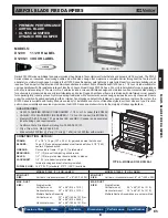
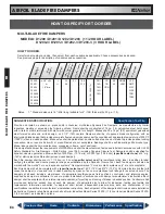
HOW TO SPECIFY
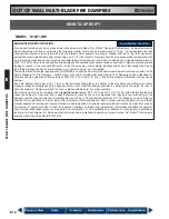
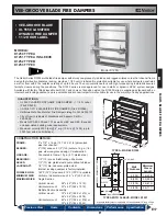
MODEL: D1201-OW
SUGGESTED SPECIFICATION:
Provide and install, as shown on plans and/or schedules, multi-blade "Out of Wall" Dynamic Fire Dampers, as manufactured by
Nailor Industries, meeting or exceeding the following criteria: Frame shall be constructed of 16 ga. (1.6) galvanized steel hat
channel with mitered corners reinforced with die-formed corner gussets for strength. Blades shall be 14 ga. (2.0) equivalent
galvanized steel formed double skin, airfoil design, on 5 1/2" (140) centers. Dampers shall be of opposed blade configuration with
an interlocking blade design that provides complete flame and smoke seal under fire conditions at an elevated temperature of
2000°F (1093°C) when in closed position. Blade axles shall be plated steel, double bolted at each end of blade to provide positive
locking connection. Hex or square friction-fit, or press-fit axles are not acceptable. Bearings shall be self-lubricating oilite bronze
type. Blade linkage shall be zero-maintenance, concealed in frame, out of airstream.
Fire dampers shall meet the requirements of NFPA 90A and shall be manufactured, tested and labeled in accordance with UL 555
Safety Standard for Fire Dampers – Sixth Edition, June 1999, including Dynamic Closure Test. Dampers shall be classified for
dynamic closure against an airflow velocity of 2000 fpm (10.16 m/s) at 4" w.g. (1 kPa) static pressure differential (across closed
damper).
Each fire damper shall bear a UL 1 1/2 hour fire resistance rating label, in addition to label verifying the airflow and closure
pressure ratings as established by the Dynamic Closure Test. Each fire damper shall also be marked with the words "For use in
dynamic systems". Dampers marked "For use in static systems only" are not acceptable.
Each fire damper shall be complete with a
(specifier select one)
165°F (74°C)
or
212°F (100°C) UL Listed fusible link that will
cause the damper to close and lock in closed position by means of an over center/knee lock linkage for assured closure. Fire
dampers shall be supplied with factory installed sleeves of 20 ga. (1.0) galvanized steel with 3/4" (19) flange on one end. Sleeves
shall be factory insulated on all four sides with intumescent thermal insulation. Each damper shall be supplied with an internal
manual quadrant for setting and locking of blades in desired position. Contractor shall provide and install an access door at each
fire damper, of appropriate size to allow for inspection, testing and fusible link replacement. Information submitted for approval
shall include independent pressure drop data and confirmation of UL qualifications in addition to manufacturer’s installation
instructions. Each shipment of fire dampers shall include same installation instructions. Dynamic rated "Out of Wall" fire dampers
shall be Nailor Industries Model D1201-OW.
Previous View
Contents
Dimensions
Performance
Specification
Home
Specification Text File

