8
5.
Remove the 2 pcs screws at the back of the ring.
7
.
Remove
total of 8 s crews to open the cabinet.
Always replace the old gasket with
a new gasket before assembly to avoid air leakage between the baffle and
cabinet.
(Location # 31 Exploded View).
6
.
Split the ring apart allowing space to form between the ring and cabinet.
Push the ring toward the baffle and place two pieces of lint free cloth between
the ring and cabinet. Carefully remove the ring from the cabinet without
scratching the cabinet.
Содержание VISO 1
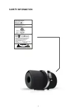
Страница 2: ...2 SAFETY INFORMATION 3 Contains Contains transmitter module ...
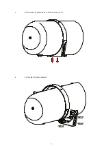
Страница 7: ...7 3 Remove the 2 pcs M6 screws at the bottom of the unit 4 Pull out the I O stand assembly ...
Страница 13: ...13 PCB LAYOUT MCU BOARD PSU BOARD ...
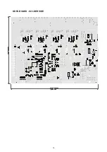
Страница 15: ...15 DDFA BOARD SOLDER SIDE ...
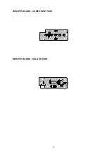
Страница 16: ...16 REMOTE BOARD COMPONENT SIDE REMOTE BOARD SOLDER SIDE ...
Страница 17: ...17 KEY BOARD COMPONENT SIDE KEY BOARD SOLDER SIDE ...
Страница 40: ...40 MCU U2 U3 U9 MCU Q1 Q2 MCU U4 U5 U8 MCU U6 ...
Страница 42: ...42 PSU U1 PSU Q1 PSU U2 ...
Страница 43: ...43 IO U1 CONN 2 U2 PSU U5 PSU U3 DDFA Q3 ...
Страница 44: ...44 DDFA Q4 DDFA Q5 DDFA Q6 ...
Страница 45: ...45 DDFA Q7 Q18 DDFA Q8 DDFA Q17 Q19 DDFA U1 ...
Страница 47: ...47 DDFA U11 U13 DDFA U15 DDFA U10 U12 U14 DDFA U16 DDFA U19 ...
Страница 48: ...48 REMOTE Q1 CONN 2 U4 REMOTE IC101 DDFA U20 ...
Страница 54: ...53 PACKING DIAGRAM PARTS LIST 2 1 4 3 5 6 7 9 8 10 11 12 14 16 15 17 13 18 19 7 10 ...
Страница 71: ...55 SERVICE MANUAL VISO 1 BT Wireless Digital Music System NAD ELECTRONICS LTD TORONTO ...


