


IDENTIFICATION OF CONTROLS
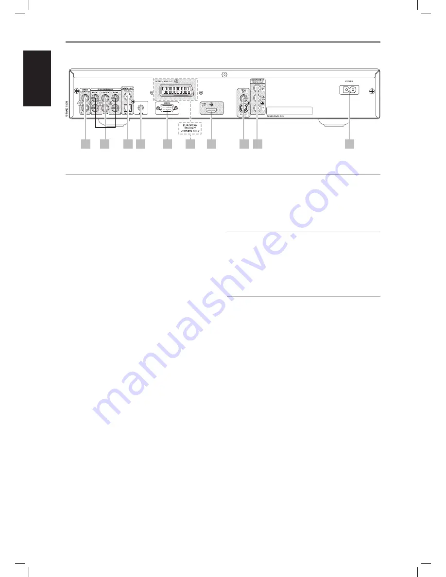
rear panel
1 mixed audio out:
Connect to the corresponding analog audio
input of an amplifier, receiver or stereo system.
2 5.1ch audio out:
The T 535 contains a multi-channel decoder. It
enables playback of discs recorded in multi-channel surround without
the need for an optional decoder.
Connect to the corresponding multi-channel audio input of a receiver
or a processor.
3 digital out (coaxial, optical):
Connect the optical or coaxial
digital OUT ports to the corresponding S/PDIF digital input of a
recording component such as a CD recorder, DAT deck, computer
soundcard or other digital processors.
4 ir in:
This input is connected to the output of an IR (infrared) repeater
(Xantech or similar) or the IR output of another component to allow
control of the T 535 from a remote location. Most NAD products with IR
OUT are fully compatible with the T 535.
5. rS-232:
Connect this interface via RS-232 serial cable (not supplied)
to any Windows® compatible PC to allow remote control of the T 535
through NAD’s proprietary PC software or other compatible external
controllers.
Please log on to www.nadelectronics.com/software for the latest PC
interface control software.
NAD is a certified partner of AMX and Crestron and fully supports these
external devices. See your NAD audio specialist for more information.
6. Scart/rgb out (euro model/pal only):
Connect the T 535’s
[SCART/RGB OUT] to the SCART/RGB video input of a compatible video
monitor/TV. Be sure to observe the correct orientation of the SCART/
RGB plug.
7 hdmi out:
Using a HDMI cable (not supplied), connect the HDMI OUT
jack to the corresponding HDMI input jack of an HDTV, a projector or an
A/V Receiver.
NOTES
• Toggle the HDMI button of DVD 9 remote control to turn ON or OFF
HDMI output. When turned ON, “HDMI ON” will be displayed in the VFD
followed by the applicable resolution setting.
• There will be no component video output at “HDMI ON”.
• HDMI button in the DVD 9 remote control will not elicit any response if
the HDMI cable is either unplugged from the HDMI OUT terminal or not
connected to a HDMI-capable TV/monitor.
WARNING
Before connecting and disconnecting any HDMI cables, both the T 535
and the ancillary source must be powered OFF and unplugged from the
AC outlet. Failure to observe this practice may cause permanent damage
to all equipment connected via HDMI sockets.
8 video out/S-video out:
Connect to video input of the monitor/
television using quality dual-RCA and/or S-Video cables designed for
video signals. In general, the S-Video connection is superior and should
be used if your TV/monitor provides the corresponding input.
9 component video out:
Connect the T 535’s COMPONENT VIDEO
OUT to the component video input of a compatible video monitor/TV
or an A/V Receiver with applicable component video input. Be sure to
observe consistency in connecting the appropriate Y, Cb/Pb, Cr/Pr jacks
to the corresponding sources/inputs. Do not rely purely on the color
coding of the jacks, which may not always be consistent among brands.
The T 535’s component-video output is a fully wide-band output,
compatible with all HDTV formats. On-screen display menu is also
shown at component video output.
10 ac power inlet:
Connect to the supplied IEC-standard removable
AC power cord or a compatible cord.
3
4
5
6
7
8
9
1
2
10
ATTENTION!
Please make sure that the T 535 is powered off or unplugged before making any connections. It is also advisable to power-down or unplug all associated
components while making or breaking any signal or AC power connections.
8
EN
G
LIS
H
FR
A
N
Ç
A
IS
ES
PA
Ñ
O
L
IT
A
LIA
N
O
D
EU
TS
CH
N
ED
ER
LA
N
D
S
SV
EN
SK
A
РУ
СС
К
И
Й
T535_eng_OM_v07.indd 8
16/7/07 08:12:20


