CYLINDRICAL BROOMS ASSEMBLY
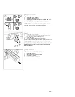
Figure 21
1.
Connect the battery connector.
2.
Turn the key into position ON.
3.
Move the switch to raise the base.
4.
Turn the key into position OFF and take it off from the
instrument board.
5.
Take off the side splash guards (see ASSEMBLY AND
DISASSEMBLY ORREGULATION SIDE SPLASH GUARDS
OFTHE WASHING/SCRUBBING BASE).
ATTENTION: To carry out the brush assembly operation with the
current connected could cause serious damage to machine and
persons
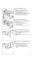
Figure 22
6.
With the base in UP position unfasten, by pushing downwards
and then outwards, the two movable supports (1).
7.
Insert the broom into the tunnel till you block it in the holder
hub, keeping the “v” shaping as in the picture.
8.
Insert the idle hub of the movable support into the brooms and
into the spring.
9.
Push the support downwards, and then inwards to refasten in the
bayonet cap.
10. Regulate the brushes adjustment with the screw (2)
11. Repeat the operation also for the second support.
12. Reassemble the side splash guards (see ASSEMBLY AND
DISASSEMBLY OR REGULATIONSIDE SPLASH GUARDS
OF THEWASHING/SCRUBBING BASE).
ATTENTION: Use gloves to protect your hands when performing the
steps listed above. SIDE SPLASH GUARDS ASSEMBLY
ANDDISASSEMBLY OF WASHING/SCRUBBINGBASE
Figure 23
This operation is to be made with the base down.
1.
Take off the pin (1).
2.
Remove the pin (2).
3.
Position the bar in the proper support.
4.
Reassemble all parts following the above operations in reverse.
HOPPER
Figure 24
Check that the hopper is latched and locked.
- 8 -


