GM Series
TM19040 P.16/31
Step 4
Align (3) mounting bolt hole for equipment of GM with the mounting holes of the machinery, and
assemble GM into the machinery.
NOTICE
During the installation, do not hit GM with a hammer and the like.
Step 5
Insert the flat washers and the mounting bolts into (3) mounting bolt hole for equipment of GM.
NOTICE
Use the specified number of GM mounting bolts and tighten with the specified tightening torque.
Otherwise, not only GM may not provide its performance but also the customer machine and GM
may be damaged.
Step 6
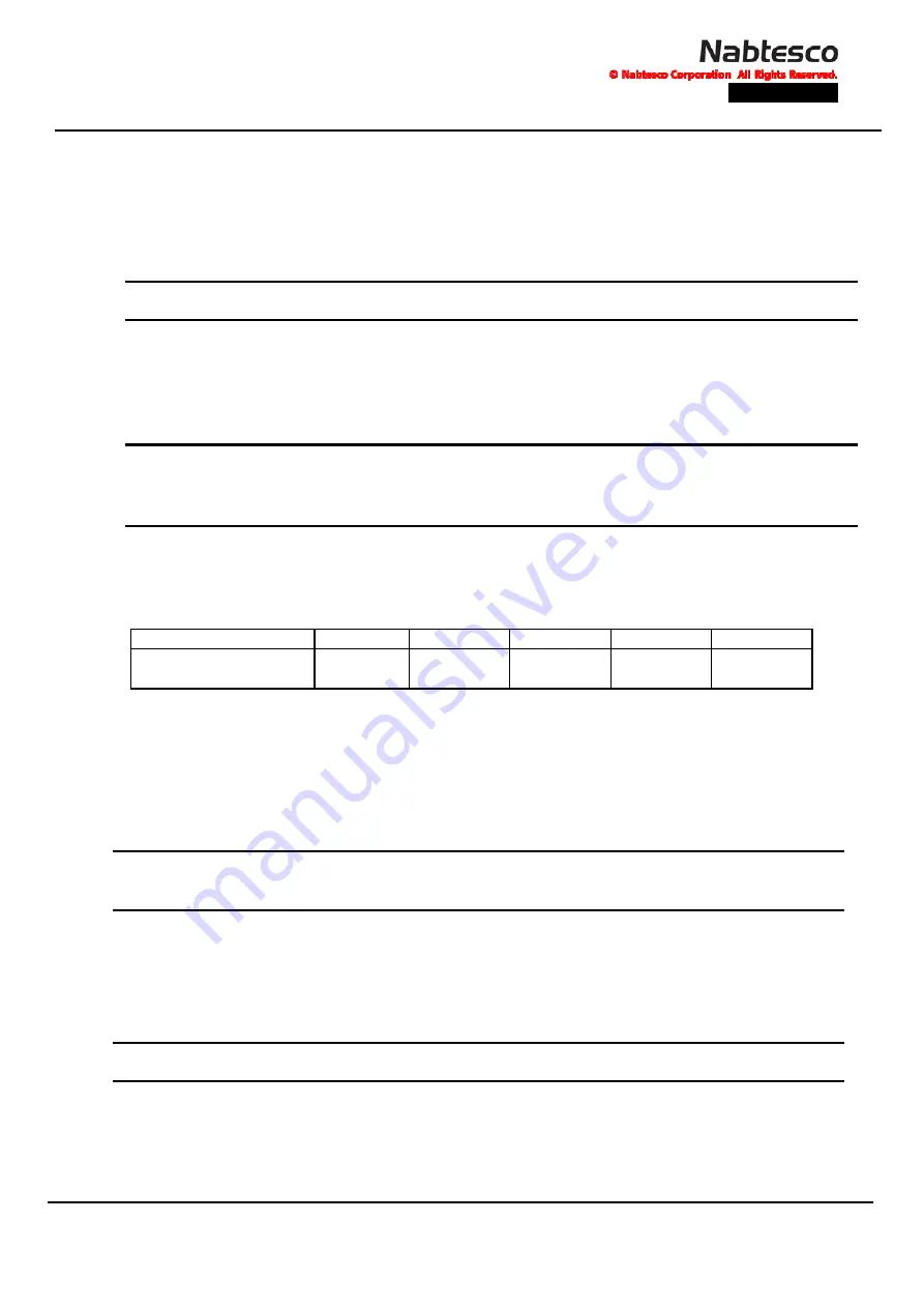
Tighten the mounting bolts for equipment uniformly with the specified tightening torque. Refer to
the confirmation notice for the quantity and bolt size.
Table 4-1
Bolt tightening torque
Bolt size
M12(P1.75)
M14(P2.0)
M16(P2.0)
M20
(
P2.5)
M24
(
P3.0)
Tightening torque [N-m]
(
Recommendation
)
102±15.7
163±24.5
252±39.2
493±78.5
709±88.3
Step 7
Check that there are no burrs or dirt on (4) mounting surface for driving part of GM and GM
mounting surface of the driving part, and wipe off the antirust oil on (4) mounting surface for
driving part of GM and (5) bearing surface of the driving part.
NOTE
GM has antirust oil applied to the non-painted surfaces before shipping. To keep the transmitting
torque by bolts high, wipe off the antirust oil on the mounting surface sufficiently.
Step 8
Align (6) mounting bolt hole for driving part of GM with the mounting holes of the driving part,
and assemble the driving part into GM.
NOTICE
Please do not hit GM with a hammer or the like at the time of mounting.
Step 9
Insert the flat washers and the mounting bolt for driving part into (6) mounting bolt hole for
driving part of GM.


