background image

43

NABRICO DF-1 ND ELECTRIC WINCH Owner’s Manual

OM-DF1-017-G

DRIVESYSTEMS

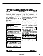
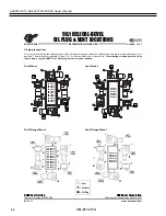
HELICAL & BEVEL REDUCER

LUBRICATION TYPES

RETAIN FOR FUTURE USE

U11000 - 1 of 2

Oil Formulation Codes
MIN-EP  -  Mineral Oil with EP Additive 

PAO-EP  -  Synthetic Polyalphaolefin Oil with EP Additive

PAO 

-  Synthetic Polyalphaolefin Oil 

PG 

-  Synthetic Polyglycol Oil 

FG 

-  Food-Grade Oil 

FG-PAO  -  Food-Grade, Synthetic Poyalphaolefin Oil

FG-PG 

-  Food-Grade, Synthetic Polyglycol Oil

Lubrication Notes

•  Avoid  using  (EP)  gear  oils  in  worm  gears  that  contain 


  sulfur-phosphorous  chemistries,  as  these  additives  can 


  react  adversely  with  bronze  worm  gears  and  accelerate 


  wear.

•  Food grade lubricants must be in compliance with FDA 212 


  CFR  178.3570  and  qualify  as  a  NSF-H1  lubricant.    Please 


  consult with lubrication manufacturer for more information.


•  When  making  a  lubrication  change,  check  with  the 


  lubrication supplier to assure compatibility and to obtain 


  recommended cleaning or flushing procedures.
•  Do not to mix different oils with different additive pack-


  ages or different base oil formulation types. Polyglycol (PG) 


  oils are not miscible with other oil types and should never 


  be  mixed  with  mineral  oil  or  polyalphaolefin  (PAO) 


  synthetic oil.

www.nord.com/docs

05.08.13

NORD Gear Corporation

Toll Free in the United States: 888.314.6673

NORD Gear Limited

Toll Free in Canada: 800.668.4378

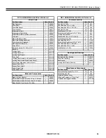
Lubrication Tables – Helical and Bevel Gear Units

Standard Oil Lubricants
ISO Viscosity

Oil Type

Ambient Temperature Range

Manufacturer Brand/Type

Notes

VG220

MIN-EP

0 to 40ºC (32 to 104º)

Mobilgear 600XP220

PAO

-35 to 60ºC (-31 to 140ºF)

Mobil SHC630

FG

-5 to 40ºC (23 to 104ºF)

Fuchs FM220

S

Optional Oil Lubricants
ISO Viscosity

Oil Type

Ambient Temperature Range

Manufacturer Brand/Type

Notes

VG460

PAO

-35 to 80ºC (-31 to 176ºF)

Mobil SHC 634

-

FG-PAO

-35 to 80ºC (-31 to 176ºF)

Mobil SHC Cibus 460

-

VG220

FG-PAO

-35 to 60ºC (-31 to 140ºF)

Mobil SHC Cibus 220

-

VG150

PAO

-35 to 25ºC (-31 to 77ºF)

Mobil SHC629

-

Grease Options (applied to greased bearings and seal cavities)
NLGI Grade

Grease Type/Thickener

Ambient Temperature Range

Manufacturer Brand/Type

Notes

NLGI 2

Standard (Li-Complex)

-30 to 60ºC (-22 to 140ºF)

Mobil Grease XHP222

High Temp (Polyurea)

-40 to 80ºC (-40 to 176ºF)

Mobil / Polyrex EP 2

Food-Grade (Polyurea)

-30 to 40ºC (-22 to 104ºF)

Mobil SHC Polyrex 222

S

S

 Stocked Lubricants

Œ

 Standard product on serviceable gear units



 Standard product on maintenance free gear units

IMPORTANT NOTES

•  The  “Ambient  Temperature”  is  intended  to  be  an  operation  guideline  based  upon  the  typical  properties  of  all  the 


  lubricant.  The viscosity and other properties of the lubricant change based upon load, speed, ambient conditions, and 


  reducer operating temperatures. The user should consult with their lubrication supplier & NORD gear before considering 


     changes in oil type or viscosity.
•  To prevent reducer overheating, observe the maximum operating oil temperature limits:
  Mineral Oil: 80-85 ºC (176 – 180 ºF).
  Synthetic Oil: 105 ºC (225 ºF).
•  In the following instances, please consult NORD for specific recommendations:
     √   Gear units will operate in high ambient temperature conditions exceeding 40 ºC (104 ºF).
     √   Gear units will operate in cold ambient temperature conditions approaching 0 ºC (32 ºF) or lower.
     √   Lower than an ISO VG100 viscosity oil is being considered for a cold-temperature service.
     √   Fluid grease is required for lubricating the gear unit. 
•  Observe the general lubrication guidelines outlined in user manual U10750.

Содержание DF-1 Series

Страница 1: ...OM DF1 017 G NABRICO DF 1 ND Electric Winch Owner s Manual ...

Страница 2: ...THIS PAGE IS INTENTIONALLY LEFT BLANK ...

Страница 3: ... 19 B 1 TYPICAL CONTROL BOX INFORMATION 20 C 1 DIMENSIONAL SHAFT MOUNTED 33 C 2 PARTS BREAKDOWN SHAFT MOUNTED 34 C 3 GEARMOTOR TECHNICAL INFORMATION SHAFT MOUNTED 38 D 1 DIMENSIONAL FLANGE MOUNTED 56 D 2 PARTS BREAKDOWN FLANGE MOUNTED 57 D 3 GEARMOTOR TECHNICAL INFORMATION FLANGE MOUNTED 59 E 1 DINGS ELECTRIC BRAKE TECHNICAL INFORMATION 63 F 1 DINGS BRAKE PREVIOUS VERSION 67 PRODUCT WARRANTY 71 PR...

Страница 4: ...Improper installation or incorrect or unsafe use could result in injury or death to persons or cause equipment failure or damage Recommended Information for Safe Operation CAUTION Check lubrication before use Do not apply tension to the winch unless there are 5 complete wraps of rope on the drum Do not operate the equipment unless you have a firm stance on a non slippery surface Do not wrap the wi...

Страница 5: ... water package standard on all power winches Stainless or silicon bronze fasteners 3 ply conveyer belt covers damage and corrosion resistant 3 tooth locking dog with large release and fail safe disc brake NEMA motor design with helical bevel gearbox Heaviest winch in its class Hot dipped galvanized Variable frequency drive option available Amp draw limits variable speeds and motor protection Made ...

Страница 6: ...e weight and holding capacity of the winch and ultimate capacity of the wire and the forces likely to occur during operation A qualified professional should inspect or design the foundation to insure that it will provide adequate support 1 2 2 Locate the winch in a suitable area free of traffic and obstacles The winch should also be visible during entire operation Keep in mind that the winch needs...

Страница 7: ...coming misaligned from heat distortion during the application of the seal weld 1 2 6 Next apply a seal weld to the mounting fixture to permanently secure it to the deck The seal weld will prevent corrosion from occurring between the mounting fixture and mounting surface 1 2 7 Inspect the winch immediately following installation This inspection will give a good starting record of the winch conditio...

Страница 8: ...s grounded before electrical power is connected 1 3 4 Refer to Appendix B 1 for typical connection between motor and control box 1 3 5 Ensure that the correct power supply agrees with the motor rating before connecting power to the winch Do not operate the winch until proper power is supplied to the motor 1 3 6 Before operation of the winch remove the plastic plug from the gearbox breather 1 3 7 T...

Страница 9: ...ION Remember to always wear the proper protective equipment when handling the wire rope 1 4 4 Rotate the U bolt so it is at the bottom of the winch and insert the new wire rope end under the winch drum and through the U bolt from the front of the winch so that approximately 3 to 4 inches extend through the U bolt 1 4 5 Ensure that the wire rope remains in the U bolt and rotate the drum around so t...

Страница 10: ...wrapping the wire rope until there are at least 5 complete wraps on the winch drum These wraps serve as an anchor and must remain on the drum at all times WARNING In order for the winch to attain its full holding capacity 5 complete wraps of the wire rope must be on the winch drum at all times Also make sure the rope is installed securely to the drum A poorly secured wire rope could come loose fro...

Страница 11: ... OUT button located on the control box or remote operator station Some tension should be kept on the wire rope during unreeling to minimize rope fouling on the drum 2 1 1 4 To stop the wire rope release the IN or OUT button this will automatically engage the electric brake located on the winch motor As with any electric brake there is a slight delay approx 0 03 seconds between the IN or OUT button...

Страница 12: ...ge the motor brake by turning the lever located on the outside of the brake 90 degrees The locking pawl should now be holding the load applied to the winch 2 1 2 9 While maintaining control of the brake release lever and manual crank rotate the locking pawl handle up relieving the locking dog engagement see fig 3a The winch should now be ready to be operated manually It is recommended to have more...

Страница 13: ...POSITION SCALE 2 1 0 STOWED POSITION SCALE 2 1 0 DRAWING NUMBER D SCALE MATERIAL THIS DRAWING IS THE PROPERTY OF NABRICO TRINITY MARINE PRODUCTS INC AND IS NOT TO BE COPIED OR THIRD ANGLE PROJECTION 1 1 SHAFT ASSEMBLY BUSHING HEX JAM LOCK NUT FIGURE 4 EMERGENCY OPERATION ...

Страница 14: ...Also check to make sure the wire rope is in good condition 3 1 1 6 While equipment is running listen for unusual noises and look for signs of damage Visually inspect the wire rope to ensure that it winds evenly onto the drum Make sure the winch responds properly to control device s and that the brake operates correctly 3 1 2 Periodic Inspection 3 1 2 1 Periodic inspections should occur whenever eq...

Страница 15: ...E HAS A MINIMUM DIAMETER OF 45 64 0 7031 FIGURE 5 WIRE ROPE DIAMETER CAUTION Remember to always wear the proper protective equipment when handling the wire rope 3 1 3 2 Inspect the entire length of wire cable for bent or crushed areas broken or cut wires corrosion and other damage If any defect or damage is found the cable must be replaced 3 1 3 3 Inspect end connections and fittings for corrosion...

Страница 16: ...ns Lubricate while gears are rotating slowly 3 2 3 Drive gear teeth should be coated at least once a month Application with an aerosol can is recommended for uniform coverage Graphite or other dry type lubricant should be used instead of gear grease when the winch is subjected to large amounts of foreign material such as coal dust Always keep gear teeth as free of foreign material as possible WARN...

Страница 17: ...tion of dirt 3 3 1 3 Remove all unnecessary objects from the area surrounding the equipment to prevent hazardous situations from occurring 3 3 2 Storing the Equipment 3 3 2 1 Lubricate the equipment as necessary to help prevent rust and corrosion during storage Add a rust preventive for long term storage 3 3 2 2 Seal the equipment in plastic if possible to help prevent rust corrosion and other dam...

Страница 18: ...e fleet angle will be equal on each side of the centerline of rope travel For a smooth drum a maximum fleet angle of 1 1 2 degrees is recommended When the drum is grooved to suit the wire rope the fleet angle should not exceed 2 degrees Example Fleet Angle Calculation for 36 Chain Drive Barge Moving Winch 36 Chain Drive Moving Winch a 18 b x distance to be determined A 1 5 minimum for a smooth dru...

Страница 19: ...ARS ENDURATEX EP 220 OPEN GEARING SPRAY CAN EUREKA FLUID FILM SPRAY MOBILTAC E LUBRIPLATE OPEN GEAR SHEILDING GREASE FITTINGS PEERLESS LLG 2 PRESERVATIVE TREATMENT MOBILARMA 524 SUMITOMO NORD AND SEW GEARBOXES USE MANUFACTURER S RECOMMENDATIONS SLEWING BEARINGS DF 559 WINCH AQUA SHIELD Note Lubricant manufacturers shown are not exclusive recommendations Consult your lubricant source for more detai...

Страница 20: ...20 NABRICO DF 1 ND ELECTRIC WINCH Owner s Manual OM DF1 017 G B 1 TYPICAL CONTROL BOX INFORMATION ...

Страница 21: ...21 NABRICO DF 1 ND ELECTRIC WINCH Owner s Manual OM DF1 017 G ...

Страница 22: ...22 NABRICO DF 1 ND ELECTRIC WINCH Owner s Manual OM DF1 017 G ...

Страница 23: ...23 NABRICO DF 1 ND ELECTRIC WINCH Owner s Manual OM DF1 017 G ...

Страница 24: ...ON CAUTION CAUTION CAUTION SHOCK RELAY SHOCK RELAY SHOCK RELAY SHOCK RELAY TSB TSB TSB TSBS S S SA A A A Series Series Series Series E E E EH H H HF F F FS S S SA A A A05 05 05 05 0601 0601 0601 0601 4 4 4 4 20 20 20 201 1 1 13 3 3 3 1 1 1 12 2 2 2 1 1 1 1 24 NABRICO DF 1 ND ELECTRIC WINCH Owner s Manual OM DF1 017 G ...

Страница 25: ... A 25 NABRICO DF 1 ND ELECTRIC WINCH Owner s Manual OM DF1 017 G ...

Страница 26: ... 72 61 26 NABRICO DF 1 ND ELECTRIC WINCH Owner s Manual OM DF1 017 G ...

Страница 27: ... 1 1 2 3 Ω 27 NABRICO DF 1 ND ELECTRIC WINCH Owner s Manual OM DF1 017 G ...

Страница 28: ... 63 2 M4 Attachment 28 NABRICO DF 1 ND ELECTRIC WINCH Owner s Manual OM DF1 017 G ...

Страница 29: ... 1 1 1 1 1 1 2 2 2 2 29 NABRICO DF 1 ND ELECTRIC WINCH Owner s Manual OM DF1 017 G ...

Страница 30: ... uto uto uto uto eset eset eset eset 30 NABRICO DF 1 ND ELECTRIC WINCH Owner s Manual OM DF1 017 G ...

Страница 31: ... 31 NABRICO DF 1 ND ELECTRIC WINCH Owner s Manual OM DF1 017 G ...

Страница 32: ... 1 1 1 1 2 2 2 2 3 3 3 3 32 NABRICO DF 1 ND ELECTRIC WINCH Owner s Manual OM DF1 017 G ...

Страница 33: ... E ØF G ØH DF 1 30 22 19 3 8 23 39 57 1 2 10 3 4 11 16 DF 1 40 23 1 4 20 1 8 24 46 1 8 70 12 3 4 11 1 4 19 DF 1 50 23 1 4 20 1 8 24 46 1 8 72 12 3 4 11 1 4 19 DF 1 65 30 23 1 8 27 55 1 2 81 14 10 5 8 24 DF 1 100 30 22 3 8 27 7 8 55 5 8 80 5 8 14 10 5 8 24 NABRICO nabrico marine com 615 442 1300 C 1 DIMENSIONAL SHAFT MOUNTED ...

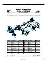
Страница 34: ...34 NABRICO DF 1 ND ELECTRIC WINCH Owner s Manual OM DF1 017 G C 2 PARTS BREAKDOWN SHAFT MOUNTED ...

Страница 35: ...08 Locking Pawl Post 1 101510 Locking Pawl Sleeve 1 101511 Part Description Qnt y Part s Drive Shaft 1 101530 Intermediate Gear Bushing 1 69973 Locking Pawl Handle Left Hand Winch 1 101582 Drum Gear Bushing 1 82511 Locking Pawl Handle Right Hand Winch 1 101583 Ball Bearing 2 84662 Cover Plate side mount motor cut out 1 101603 Locking Pawl Sleeve Bushing 1 101512 Keeper Plate BIG 1 101650 Keeper Pl...

Страница 36: ...36 NABRICO DF 1 ND ELECTRIC WINCH Owner s Manual OM DF1 017 G ...

Страница 37: ...1 101584 Locking Pawl Handle Right Hand Winch 1 101585 Part Description Qnt y Part s Cover Plate side mount motor cut out 1 101603 Drum Gear Bushing 1 71676 Top Plate 1 101605 Intermediate Gear Bushing 1 71854 Drive Shaft Collar 1 105006 Ball Bearing 2 84662 Side Plate keeper side 1 105008 Locking Pawl Sleeve Bushing 1 101517 Side Plate locking pawl side 1 105009 Pipe Separator Rod SS 6 105010 Dri...

Страница 38: ... or damage in shipment must not be deducted from the NORD invoice nor should payment of the NORD invoice be withheld awaiting adjustment of such claims as the carrier guarantees safe delivery NORD will try to assist in collecting claims for loss or damage during shipment how ever this willingness on our part does not remove the trans portation company s responsibility in reimbursing you for col le...

Страница 39: ...ons contained in the safety notes or related operating instructions WARNING NORD assumes no liability for personal injury equipment damage or malfunctions resulting from failure to comply with any installation safety notes The appli cable national regional and local work regulations and safety requirements must also be complied with Failure to comply with any safety notes or regulations may result...

Страница 40: ... safeguard against injury Surfaces of motors and gear units may become hot during operation or shortly after start up In some instances additional protection against accidental contact may be necessary Use caution to avoid burns or serious injury GENERAL WARNINGS 3 Observe published performance range nameplate data Observe the data on all reducer nameplates and verify published ratings for the NOR...

Страница 41: ...he lubricant If in doubt about which lubricant is needed for a certain applica tion please contact NORD Gear 3 Lubrication replacement If the gear unit is filled with mineral oil the lubricant should be replaced at least after every 10 000 operating hours or after every two years If the gear unit is filled with synthetic oil the lubricant should be replaced at least after every 20 000 operating hour...

Страница 42: ... additional oil as needed The minimum acceptable oil level is 0 15 in 4mm below the oil level hole 8 Oil plug locations All gear units are assembled with the oil fill level oil drain and vent plugs installed in their proper locations according to the specified mounting position All standard plugs are metric and utilize sealing gaskets between the head of the plug and the reducer housing 9 Drain and ...

Страница 43: ... Fuchs FM220 S Optional Oil Lubricants ISO Viscosity Oil Type Ambient Temperature Range Manufacturer Brand Type Notes VG460 PAO 35 to 80ºC 31 to 176ºF Mobil SHC 634 FG PAO 35 to 80ºC 31 to 176ºF Mobil SHC Cibus 460 VG220 FG PAO 35 to 60ºC 31 to 140ºF Mobil SHC Cibus 220 VG150 PAO 35 to 25ºC 31 to 77ºF Mobil SHC629 Grease Options applied to greased bearings and seal cavities NLGI Grade Grease Type ...

Страница 44: ... 220N PG 25 to 60ºC 13 to 140ºF Mobil Glygoyle 220 Tivela S220 Alphasyn PG220 Renolin PG220 Klübersynth GH 6 220 FG 0 to 40ºC 32 to 104ºF Mobil DTE FM 220 N A N A Fuchs FM220 N A FG PAO 25 to 60ºC 13 to 140ºF Mobil SHC Cibus 220 N A N A Cassida GL220 Klüberoil 4 UH 1 220N FG PG 25 to 60ºC 13 to 140ºF Mobil Glygoyle 220 N A N A Cassida WG220 Klübersynth UH1 6 220 VG460 MIN EP 0 to 40ºC 32 to 104ºF ...

Страница 45: ... 26 0 SK 9072 1 12 7 12 0 29 1 27 5 34 9 33 0 40 7 38 5 20 1 19 0 27 5 26 0 SK 9082 1 22 2 21 0 57 0 54 0 70 0 66 0 85 0 80 0 40 2 38 0 55 0 52 0 SK 9086 1 38 0 36 0 82 0 78 0 96 0 91 0 113 107 56 0 53 0 80 0 76 0 SK 9092 1 42 3 40 0 137 130 163 154 185 175 87 0 82 0 96 0 91 0 SK 9096 1 85 0 80 0 198 187 204 193 272 257 119 113 165 156 Oil Levels shown apply to base models and gear units ending in...

Страница 46: ... docs 06 01 11 NORD Gear Corporation Toll Free in the United States 888 314 6673 NORD Gear Limited Toll Free in Canada 800 668 4378 M3 H2 B5III SK 9012 1 SK 9016 1 SK 9022 1 SK 9032 1 SK 9042 1 SK 9052 1 SK 9072 1 SK 9082 1 SK 9086 1 SK 9092 1 SK 9096 1 M1 H1 B5I M2 H4 B5 M5 H5 V1 M4 H3 B5II M6 H6 V3 SK 9013 1 SK 9017 1 SK 9023 1 SK 9033 1 SK 9043 1 SK 9053 1 M1 H1 B5I M2 H4 B5 M5 H5 V1 M3 H2 B5II...

Страница 47: ...and the mating solid shaft clean of any lubricants and dirt Only use solvent if the parts feel oily to the touch after wiping with a clean rag 7 Slide the reducer onto the solid shaft until it is about half way through 8 Lubricate the remaining portion of the solid shaft with a 2 grease where it will be inserted into the hollow shaft 9 Tighten the locking screws in a circular pattern Refer to Tabl...

Страница 48: ... 2 Loosen the outer collars from the tapered inner ring This may require tapping the bolts with a soft faced hammer or prying lightly between the outer collars 3 Remove hollow shaft reducer from solid shaft Preparation for Re Use 1 Disassemble and thoroughly clean all parts Wire brush to remove any excessive rust or dirt 2 Lubricate the taper of the outer collars and of the inner ring with Molycot...

Страница 49: ... sides of the torque arm bracket WARNING It is the responsibility of the machine builder to design a support bracket of adequate strength and rigidity and supply an appropriate tightening bolt assembly Failure to do so may result in injury caused from a damaged or broken torque reaction assembly 4 Installation of a right angle reducer with torque arm A Make sure the Torque Arm D is mounted in the ...

Страница 50: ...ture Loose hold down bolts Tighten bolts Failure of bearings May be due to lack of lubricant Replace bearing Clean and flush reducer and fill with recommended lubricant Overload Check rated capacity of reducer Insufficient lubricant Level of lubricant in reducer not properly maintained Check lubricant level and adjust to factory recommended level Output shaft does not turn Internal parts are broken o...

Страница 51: ...702 Pinion Shaft 703 Bevel Gearset 705 Gear 706 Pinion 707 Output Shaft 709 Oil Seal 710 Oil Seal 711 Snap Ring 712 Shim 713 Anti Friction Bearing 714 Gasket 715 Inspection Cover 716 Spacer 717 Vent Plug 718 Gasket 719 Bolt 720 Key 721 Snap Ring 722 Anti Friction Bearing 724 Retaining Washer 725 Lock Washer 726 Bolt 729 Thrust Washer 731 Snap Ring 732 Gasket 733 Key 734 Oil plug 735 Gasket 736 Sna...

Страница 52: ...15 Inspection Cover 716 Spacer 717 Vent Plug 718 Seal 719 Bolt 720 Key 721 Snap Ring 722 Anti Friction Bearing 724 Washer 725 Lock Washer 726 Bolt 729 Thrust Washer 731 Snap Ring 732 Gasket 733 Key 734 Oil plug 735 Gasket 736 Snap Ring 737 Anti Friction Bearing 738 Anti Friction Bearing 739 Snap Ring 740 Bore Plug 741 Shim 742 Thrust Washer 743 Gearcase 745 Anti Friction Bearing 746 Key 747 Shim 7...

Страница 53: ... 1 905 Bearing 1 906 Preload Spring 1 907 Terminal Box Frame 1 907 1 Screw 4 908 Terminal Box Cover 1 908 1 Screw 4 909 Gasket Terminal Box Frame 1 910 Gasket Terminal Box Cover 1 916 Stator 1 918 Key 1 919 Retaining Ring 1 920 Oil Plug 1 920 921 902 1 916 910 907 909 908 960 961 907 1 908 1 905 906 904 902 6 919 TBLK TBLK 1 902 902 1 923 923 902 1 902 2 902 900 940 1 940 952 939 933 918 932 1 932...

Страница 54: ...Siemens Frames 200 230 460V 60Hz 3Ø 200 400V 50Hz 3Ø 190 380V 60Hz 3Ø 120094410 NORD Frames 63 225 460 800V 60Hz 3Ø 230 400V 50Hz 3Ø 208 360V 60Hz 3Ø 400 690V 50Hz 3Ø 332 575V 60Hz 3Ø NORD 2 SPEED MOTORS SINGLE WINDING 4 2 8 4 POLE T4 2U T5 2V T6 2W T1 1U T2 1V T3 1W SINGLE WINDING 2 SPEED MOTORS T4 2U T5 2V T6 2W T1 1U T2 1V T3 1W HIGH SPEED LOW SPEED L1 L2 L3 L1 L2 L3 Customer Supplied Starter C...

Страница 55: ...OLING FAN F OPTION BLOWER COOLING FAN 120095450 120095250 120095240 120095230 120095220 FROM MOTOR TERMINAL BLOCK TO CONTROL DEVICE MAX OPERATING VOLTAGE 2 5V SWITCH TEMP 155 C RESPONSE TIME 5 SECONDS FROM MOTOR TERMINAL BLOCK TO CONTROL DEVICE NC NORMALLY CLOSED CONTACTS RATED 1 6A AT 2 50 VAC 6 500 VAC WORKING RANGE AUTOMATIC RESET AT 30 15 C TEMP DROP FROM MOTOR TERMINAL BLOCK TO CONTROL DEVICE...

Страница 56: ...D 1 DIMENSIONAL FLANGE MOUNTED Right Hand Winch Shown Left Hand Winch Opposite Model Length A Width B Height C Overall Length D Drum Dia E Drum Width F DF 1 40 14 105 8 Weight Flange Dia G 383 16 551 2 231 8 30 24 Part Number 83396 83397 1 850 lbs D B A C F ØE ØG ...

Страница 57: ...57 NABRICO DF 1 ND ELECTRIC WINCH Owner s Manual OM DF1 017 G D 2 PARTS BREAKDOWN FLANGE MOUNTED ...

Страница 58: ... 3 SS 1 14595 Key drive pinion 1 2 SQ x 4 1 4 1 87630 Hex Head Bolt 1 2 x 1 SS 6 70521 Locking Dog Handle 15 Length 1 93732 Lock Washer 1 2 SS 9 70584 Base Bar 2 101501 Locking Pawl 1 101508 Locking Pawl Post 1 101510 Locking Pawl Sleeve 1 101511 Top Plate 1 101604 Keeper Plate BIG 1 101650 Part Description Qnt y Part s Keeper Plate small 1 101651 Intermediate Gear Bushing 1 69973 Cable Guard Plat...

Страница 59: ...itioning the reducer while the hold down bolts are properly secured once the reducer is secured the tenon helps prevent movement of the reducer and it helps locate the center of the reducer output shaft Table Flange Pilot Tolerance Above ø in To Including ø in Tolerance in ISO 286 2 Fit Class 1 969 3 150 0 0005 0 0003 j6 3 150 4 724 0 0005 0 0004 j6 4 724 7 087 0 0006 0 0004 j6 7 087 9 055 0 0006 ...

Страница 60: ...cations 4 Foot flange reducer housings Some gear reducer housings are available with a foot and an output flange Units with a foot and a B5 Flange are desig nated with the suffix XF after the primary model number and units with a B14 face flange are designated with the suffix XZ after the primary model number When a gear unit is provided with both a foot and a flange the foot is consider the prima...

Страница 61: ...02 Pinion Shaft 703 Bevel Gearset 705 Gear 706 Pinion 707 Output Shaft 708 Key 709 Oil Seal 710 Oil Seal 711 Snap Ring 712 Shim 713 Anti Friction Bearing 714 Gasket 715 Inspection Cover 716 Spacer 717 Vent Plug 718 Gasket 719 Bolt 720 Key 721 Snap Ring 722 Anti Friction Bearing 723 Bore Plug 729 Thrust Washer 731 Snap Ring 732 Gasket 733 Key 734 Oil plug 735 Gasket 736 Snap Ring 737 Anti Friction ...

Страница 62: ...13 Anti Friction Bearing 714 Gasket 715 Inspection Cover 716 Spacer 717 Vent Plug 718 Gasket 719 Bolt 720 Key 721 Snap Ring 722 Anti Friction Bearing 723 Bore Plug 729 Thrust Washer 731 Snap Ring 732 Gasket 733 Key 734 Oil plug 735 Gasket 736 Snap Ring 737 Anti Friction Bearing 738 Anti Friction Bearing 739 Snap Ring 740 Bore Plug 741 Shim 742 Thrust Washer 743 Gearcase 744 Flange 745 Anti Frictio...

Страница 63: ...spect it carefully for damage that may have occurred during transit Do not activate the manual release without the hub inserted in the discs as doing so may result in loss of disc spline alignment GENERAL SAFETY INFORMATION NOTE These brakes are not intended for accurate positioning applications They are designed for applications that require rapid stopping and holding power such as on conveyors d...

Страница 64: ... on motor shaft with key according to dimension N per figure 1 Stamped part number on hub should face away from motor Tighten hub set screws with 13 lb ft torque 2 Remove temporary cover nut and cover 67 Set cover aside Discard temporary nut 3 If brake is supplied with a mounting face gasket 91 place gasket onto the brake mounting face 4 Place brake on motor guiding discs on hub Use caution not to...

Страница 65: ...torque gold 2 2 2 2 2 2 2 2 2 2 2 2 G070849 001 43 Washer flat 3 3 3 3 3 3 3 3 3 3 3 3 3 3 W004002 008 44 Nut adjustment 3 3 3 3 3 3 3 3 3 3 3 3 3 3 W003013 005 46 Washer magnet assembly base 2 2 2 2 2 2 2 2 2 2 2 2 2 2 W004004 018 50A Magnet Assembly three phase 1 1 1 1 1 1 1 1 1 1 1 1 1 1 H070402 XXX 50 Magnet frame three phase 1 1 1 1 1 1 1 1 1 1 1 1 1 1 K070567 001 51 Coil magnet three phase 3...

Страница 66: ... ND ELECTRIC WINCH Owner s Manual OM DF1 017 G 4740 W ELECTRIC AVE MILWAUKEE WISCONSIN 53219 414 672 7830 FAX 414 672 5354 www dingsbrakes com BK4773 3 02 2016 EXPLODED VIEW See Table 1 Figure 2 Exploded View of Brake ...

Страница 67: ...ed and spring set It uses rotating and stationary disc contact to supply positive braking action It retains quick release and setting capabilities at all times Simplicity of design has reduced maintenance to an absolute mini mum As with any electromechanical equipment however periodic inspection and adjustment will assure optimum performance As the friction disc wears the magnet gap will increase ...

Страница 68: ...on until rods are manually returned to original position or until electrical power is restored which automatically returns the release rods to the set position TORQUE ADJUSTMENT See Figures 1 3 Brake is factory set for rated torque per spring length H To increase stopping time and lower torque turn two locknuts 8 counterclockwise increasing dimension H All two springs must be set to the same lengt...

Страница 69: ...anual Release Lockwasher 2 2 2 2 2 2 W004007 007 14 Manual Release Stop Screw 2 2 2 2 2 2 G060029 001 15 Magnet Assembly with coils 3 phase 1 1 1 1 1 1 K070097 15 Magnet Assembly with coils single phase 1 1 1 1 1 1 K070335 16 Magnet Plate w o Coils 3 phase 1 1 1 1 1 1 K070024 001 16a Magnet Plate w o Coils single phase 1 1 1 1 1 1 K070027 001 17 Coil single phase 2 2 2 2 2 2 H070013 17a Coil 3 pha...

Страница 70: ...TS Brake Model Number Part Number from Tables Part Description from Tables On hub order furnish bore dia keyway dimensions On electrical parts specify voltage phase frequency REPLACEMENT BRAKE Model Number Voltage Phase Frequency Hub Bore Keyway Dimensions Mounting Horizontal or Vertical If vertical specify whether above or below motor If brake includes foot mounting bracket or adaptor specify FRI...

Страница 71: ...IES OF MERCHANTABILITY OR FITNESS FOR A PARTICULAR PURPOSE WITH RESPECT TO THE CONSTRUCTION DELIVERY AND SALE OF A NABRICO PRODUCT AND NABRICO SHALL FOLLOWING SAID DELIVERY AND SALE IN NO EVENT BE LIABLE TO BUYER OR ANY END USER FOR THE BREACH OF ANY WARRANTY GUARANTEE OR REMEDY EXPRESSED OR IMPLIED IN FACT OR IN LAW EXCEPT AS SPECIFICALLY SET FORTH ABOVE EXCEPT AS PROVIDED HEREIN NABRICO SHALL AT...

Страница 72: ...AL QUICK ACTING 4 DOG MANUAL CHOCKS CAST STEEL BUTTON ROLLER BUTTON OCEAN DOMES MILD STEEL STAINLESS STEEL BITTS DOUBLE BITT SINGLE BITT THRU DECK BITT KEVELS KEVEL CHOCK KEVEL THRU DECK KEVEL BARGE CRANES ELECTRIC OPERATION MANUAL OPERATION SUCTION BELLMOUTHS 6 SIZE 8 SIZE 10 SIZE NABRICO 1250 GATEWAY DRIVE GALLATIN TN 37066 615 442 1300 615 442 1313 fax www nabrico marine com N A B R I C O O V E...

Отзывы: