3 of 5
www.NabcoEntrances.com
GT1175U-19ElectricLockRetrofitKitQuickSetupPartsGuide
Rev2-15-18
P/NC-00299
SECTION 2: Install the Electric Lock
1.
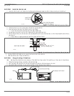
Insert (2) 3/8 -16 x 3/4 inch T-Bolts into the Channel located inside Header and turn clockwise so they do not fall out.
DN 0738
Insert T-Bolt
into Channel
Turn T-Bolt Clockwise
to Lock into Channel
Figure 3
Insert Socket Head Cap Screws into Channel
2. Obtain the Electric Lock provided within the Electric Lock Retrofit Kit.
3.
Place the Electric Lock over the (2) 3/8-16 x 3/4 inch T-Bolts.
a. Ensure the Terminal Strip is facing the Pivot side of Slide Door.
4.
Loosely secure the Electric Lock to the T-Bolts with (2) 3/8-16 Whizlock nuts.
5. Position the Electric Lock so the Strike is directly behind the Latch when the Slide door is in the Fully Closed Position. Please
a. Ensure there is a slight gap between the Strike Wall and Flat of Latch.
DN 0642
Slight Gap
(Between Strike Wall and Flat of
Latch in Full Close Posi on)
PIVOT SIDE OF DOOR
Strike Wall
Strike
Latch
Figure 4
Ensure Terminal Strip is Facing Pivot Side of Slide Door
6.
Tighten (2) 3/8-16 Whizlock nuts to secure the Electric Lock to the Channel.
7. Wire the Electric Lock. Please see Section
4.
SECTION 3: Change Handing of Slide Door
Note: Handing of the Slide Door is only necessary if the Slide Door: Opens when it should Close; or Closes when it should Open.
1.
Obtain the Handing Harness provided within the Parts Bag.
2.
Go to the Motor Harness that is connected to the Motor and the U-19 Microprocessor Control.
3.
Separate the Motor Harness to connect the Handing Harness between the connectors.
Motor Connector (6 pin)
Power Connector (4 pin)
Size: 5.2 x 20mm
Rang: 125V, 5A
Fuse Inside
No.
COLOR
SYMBOL
NO.
12
11
10
9
8
7
6
5
4
3
2
1
OUT -
OUT +
BA
SQ
62
M1
M0
H
6 B
61
7
9DC12V
Gray
Violet
Blue
Yellow
Orange
Orange
Orange
Green
White
Black
Red
Brown
COLOR
NO.
6
5
4
3
2
1
Yellow
Black
Blue
Brown
Orange
Red
USE
Encoder B Phase
Encoder Ground
Motor U Phase
Encoder A Phase
Encoder 12 VDC
Motor V Phase
USE
COLOR
NO.
4
3
2
1
Black
White
Not Used
115 VAC Hot
115 VAC Common
Not Used
WARNING
type and rang.
with a fuse of the same
against fire, replace only
For connued protecon
CAUTION
DN 0749
Handing Harness
Motor Harness & Plug
Microprocessor Control
Motor
Figure 5
Change Handing of Slide Door


