


Meikon
MAMC-XLINK – Technical Reference Manual
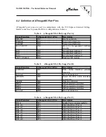
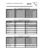
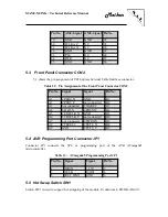
Table 10: ATmega645 Port Pin Usage (Port G)
Signal Function
ATmega645 Port G Pin
Description
/RST_IPMI
PG5
RESET input to IPMI controller
PG4
controls the yellow LED on the
front panel
PG3
controls the green LED on the
front panel
not used
PG2
pin is unconnected
LED4
PG1
controls LED 4 on the front panel
LED block
LED3
PG0
controls LED 3 on the front panel
LED block
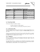
4.3 Front Panel LEDs
The front panel LEDs are divided into 2 groups:
-
the LEDs specified by the AMC.0 standard
-
a block of 4 LEDs above the PCI Express External Cable connector
4.3.1 AMC Standard LEDs
The AMC standard defines 4 LEDs, located on the lower / right side of the front panel, two of
which are mandatory, and two of which are optional. The
MAMC-XLINK
supports all of
these LEDs.
There are two general status LEDs, a blue LED, and a red LED. These LEDs are controlled
by IPMI firmware. The other two LEDs, a green LED and a yellow LED, are optional. They
are supplied, but their use depends on user’s software.
4.3.2 4 LED Block
There is a 4 LED block located above the PCI Express External Cable connector. LEDs 1 and
2 of this block show the link status of the Re-Driver PCIe lines. LEDs 3 and 4 are
programmable by the user.
All programmable LEDs are controlled by the ATmega645 microcontroller. For further
information on how to program these LEDs please refer to the ATmega325/3250/645/6450/V
Product Data Book, or turn to Meikon / N.A.T. for further assistance.


