


Introduction
1 - 6 External Locator - Front & Rear View
1.Introduction
External Locator - Front & Rear View
Figure 2
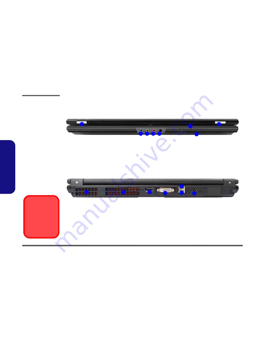
Front & Rear Views
1. LCD Latches
2. Line-In Jack
3. Headphone-Out
Jack
4. Microphone-In Jack
5. S/PDIF-Out Jack
6. LED Indicators
7. Infrared &
Consumer Infrared
Transceiver
8. Vent
9. HDMI-Out Port
10. DVI-Out Port
11. Combined eSATA/
USB Port
12. USB 2.0 Port
13. DC-In Jack
Overheating
To prevent your com-
puter from overheating
make sure nothing
blocks the vent/fan in-
takes while the com-
puter is in use.
1
1
2
3
4
5
6
7
Front
2
1
1
4
3
5
6
Rear
Содержание XMG7
Страница 1: ......


