background image

21

11. MAINTENANCE

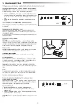
Battery of the remote control:

The batteries in the remote have an extremely long life. If the transmission range decreases, the batteries must be replaced. Batteries are not covered by the guarantee.

Please observe the following instructions for battery:

Batteries should not be treated as household waste. All consumers are required by law to dispose of batteries properly at the designated collection points. Never recharge 

batteries that are not meant to be recharged.

Danger of explosion!

Keep batteries away from children, do not short-circuit them or take them apart. See a doctor immediately, if a battery is swallowed. If necessary, clean contacts on battery 

and devices before loading. Remove flat batteries from the device immediately!

Increased risk of leakage!

Never expose batteries to excessive heat such as sunshine, fire or similar!

There is increased risk of leakage!

Avoid contact with skin, eyes and mouth. Rinse the parts affected by battery acid with plenty of cold water and consult a doctor immediately. Use only batteries of the 

same type. Remove the batteries if the device is not being used for a long time.
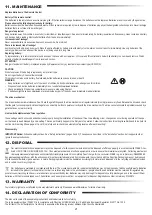
Replacing battery:

To replace battery, turn remote control around and open the case with a screwdriver. Lift cover and lift control board below. Slide battery to one side and remove. Watch 

polarity of battery! Assemble again from in reverse direction.

ATTENTION!

Danger of explosion if battery is replaced improperly. Replacement only by identical or equivalent type (CR2032) 3V.

The drive mechanism is maintenance free. Check the gate fittings and the drive mechanism at regular intervals (monthly) are securely fixed. Release the drive and check 

that the gate functions properly. Unless the gate runs smoothly it will not operate correctly with the drive mechanism. The drive cannot eliminate the problems caused by a 

gate that does not work correctly.

These settings must be checked and undertaken properly during the installation of the opener! Due to weathering, minor changes can occur during operation of the ope-

ner that need to be addressed by a new setting. This can particularly happen in the first year of operation. Follow the instructions for setting travel limits and force (refer to 

section Limit Learning Phase, pages 11 and 12) carefully and re-check the automatic safety reverse after each resetting!

IMPORTANT Notice! 

Follow the safety notices. See “Safety instructions” (pages 2 and 3). The sequence described  in the “installation” section, but in opposite order. 

Ignore the setup instructions.

Your statutory rights are not affected by this manufacturer‘s warranty. Please see www.liftmaster.eu for terms of warranty.

Our electrical and electronic equipment may not be disposed of with household waste and must be disposed of after use properly in accordance with WEEE Direc

-

tive EU: 2012/19/EU; GB UK(NI): SI 2012 nr. 19 on waste electrical and electronic equipment in order to ensure that materials are recycled.  Collecting waste elect

-

rical equipment separately means environmentally-friendly disposal and is completely free of charge for the consumer. WEEE reg. no. in Germany: DE66256568. 

Any waste packaging left over with the end consumer must be collected separately from mixed waste, in accordance with the Directive. Packaging may not be disposed 

of with household waste, organic waste or in nature. Packaging material must be separated according to its material and disposed of in the recycling containers provided 

and in certain council recycling bins.

Replace Batteries in The Remote Control

The drive mechanism

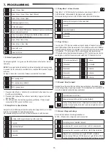
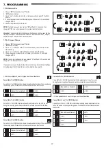
Limit switch adjustment and force regulation
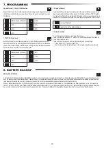
Disassembly

Our batteries are marketed in compliance with the law. The ‘crossed-out waste bin’ indicates that batteries may not be disposed of with household waste. Batteries 

included in the product (technical data). In order to avoid causing harm to the environment or people’s health, used batteries must be returned for regulated dis-

posal at council recycling centres or via retail outlets, as is prescribed by law. Batteries may only be brought for disposal once fully discharged and, in the case of lithium 

batteries, with their terminals taped over. The batteries can be easily removed from our equipment for disposal. Registration number in Germany: 21002670.

The manual consists of these operating instructions and the declaration of conformity.

The radio equipment type (TX4EVF) is in compliance with Directive 2014/53/EU and for UK with Radio Equipment Regulation SI 2017 No. 1209. 


The full text of the EU declaration of conformity is available at the following internet address: https://doc.chamberlain.de

CAUTION

Risk of explosion if the battery is replaced by an incorrect type.

Do not ingest battery, Chemical Burn Hazard.

This product contains a coin battery. If swallowed, button batteries can cause injuries, or death.

WARNING

•  Keep batteries out of sight and out of the reach of children, button/coin batteries can be dangerous for children.

•  Dispose of used button batteries immediately. Do not use defect/swallowed batteries.

•  Check periodically if the battery compartments is secure, stop using if defect.

•  If batteries might have been swallowed or placed inside any part of the body, seek immediate medical attention.

12. DISPOSAL

13. WARRANTY

14. DECLARATION OF CONFORMITY

Содержание LiftMaster LA250EVK

Страница 1: ...shandbuch für Drehtorantriebe pl Instrukcja instalacji operatora bramy skrzydłowej cs Instalační manuál pro obsluhu křídlové brány sk Inštalačný manuál k pohonu krídlovej brány sl Priročnik za namestitev upravljalnika krilnih vrat hu Swing kapu Üzemeltető Installation Manual For GB UK NI specific information on national regulations and requirements see English part of the manual ...

Страница 2: ...12 7 6 Programming and Erasing of Remote Controls Radio Accessories and myQ Devices 13 7 7 Advanced Settings 14 7 7 1 Overview Advanced Settings 14 7 7 2 Transmitter Settings 14 7 7 3 Infrared Photocells Settings 14 7 7 4 Input Settings 14 7 7 5 PartialOpeningMotor1 15 7 7 6 Delay Motor 2 in Open Direction 15 7 7 7 Delay Motor 1 in Close Direction 15 7 7 8 Timer to Close 15 7 7 9 Reversal Time aft...

Страница 3: ...d to the gate system This is also obligatory in the process of retrofitting on a manually operated gate Further a handover pack and an inspec tion book must be completed Please read the operating instructions and especially the precautions The following symbols are placed in front of instructions to avoid personal injury or damage to property Read these instructions carefully Warnings Symbols The ...

Страница 4: ...le locations The gate opener should ONLY be used if the user can see the entire gate area and is assured that it is free of obstacles and the gate operator is set correctly No one may pass through the gate area while it is moving Children must not be allowed to play in the vicinity of the gate The full protection against potential crushing or entrapment must work immediately when the drive arms ar...

Страница 5: ...x Release Key 4x Release Key 4x Installation Manual Installation Manual Remote Control 2x Control Box M10x30 Screws 4x Gate Mounting Bracket 2x Gate Mounting Bracket 2x Circlip 4x Circlip 2x Circlip pin 4x Circlip pin 2x Washer and Bolt 2x LA250EVK LA300EVK LA250EVK LA300EVK 1 Motor 1 2 Motor 2 3 Control board 4 Post bracket 5 Gate bracket 6 Infrared photocells 7 Flashing lamp 1 2 6 4 4 5 3 5 6 7 ...

Страница 6: ... installation of the gate operator LA300EVK LA250EVK 1 5 m 250 kg 2 0 m 200 kg 2 5 m 150 kg LA300EVK 2 0 m 300 kg 2 5 m 250 kg 3 0 m 200 kg mm A 100 120 140 160 180 B 100 n a 110 105 105 100 120 110 110 100 95 95 140 100 100 100 90 80 160 95 95 90 85 75 180 90 90 80 75 70 mm A 100 120 140 160 180 B 100 n a 110 105 105 100 120 110 110 100 95 95 140 100 100 100 90 80 160 95 95 90 85 75 180 90 90 80 ...

Страница 7: ...l hard stop Consider the dimensions A and B from Table 1 d Manually open and close the gate to the required positions Ensure the operator arm does not bind and gate is moving smoothly For LA300EVK please ensure that in the OPEN position the trolley is having min 25 mm free space e Make permanent connection of the gate bracket at chosen correct position 4 2 Installation with internal operator hard ...

Страница 8: ...table on page 5 for other settings 1 and 2 are operator internal hardstops 1 2 5 mm 1115 mm Spirit level 61 mm 730 mm with hardstops 750 mm w o hardstops Spirit level 1 2 3 1 x 360 4 1 a 25 mm min 25 mm min 4 1 a 4 1 b 4 1 c LA250EVK LA300EVK LA250EVK LA300EVK 5 MECHANICAL INSTALLATION ...

Страница 9: ...ing must be done by a certified electrician specialist Congratulations Herewith the mechanical installation of your gate ope rator is finished Please proceed with Programming and Basic Settings to be able to start operation Motor 2 Connection NOTE The operator wired to the MOTOR 2 terminal will always open last and close first Consider this for Basic and Advanced Settings see Programming section 1...

Страница 10: ...use IR 1 IR 2 IR 3 SYNC STBY UART LIMIT SW connectors are not used for LA units MOTOR 2 WHT GRN RED MOTOR 1 M M BAT BAT 24V BATTERY POW 24V SPEC 24VDC SYNC STBY UART LIMIT SW E LK FLA COMMAND IR SENSOR EDGE 24V BAT 8 2K SAFETY EDGE NC NO NO Stop Total Open Partial Open E LOCK MAG LOCK LAMP 1 FLASH LAMP SE SE GND GND IR3 IN3 IN2 IN1 IR2 IR1 L L N N PE AC 230V IN CTRL GND 12V TX RX 5V OP CL 24V exte...

Страница 11: ...on for 5 seconds to enter the menu AP on the display indicates the first available function in menu 2 Use and buttons to navigate between the functions 3 Press P button to select the required function 4 The default setting or previously programmed value will appear This will be indicated by flashing of value on display 5 Use or buttons to select the required value Press P button to confirm selecti...

Страница 12: ... Defines movement direction of the Motor 2 Not available for one motor application 7 4 3 Direction Motor 2 Settings Motor 2 is moving in closing direction Motor 2 is moving in opening direction Available Learning methods Before starting a Learning phase ensure that 1 Other Basic Settings are completed 2 Internal external hard stops are installed for swing gates 3 First movement will be in CLOSE di...

Страница 13: ...ing 2 actions are not used Following settings are programmed during Advanced Learning mode 1 Travel length from FULL CLOSED to FULL OPEN position 2 Opening and closing force for each motor 3 Starting positions of the Soft Stops 4 Wing delay in opening and closing position is 2 seconds Shall you need to change the delay please go to Advanced Settings Delay Motor 2 d0 and Delay Motor 1 dC NOTE To st...

Страница 14: ...f IRs is mandatory for myQ operation 2 Create an account Download the free myQ App from App Store or Google Play Store and create an account If you already have an account use your username and password 3 Register the internet gateway Enter the Serial Number located on the bottom of the internet gateway when prompted 4 Add myQ devices To add your gate operator to the registered gateway follow the ...

Страница 15: ...function defines the way Input commands from external accessories are executed Each of the 3 Inputs can be programmed individually NOTE Under settings 01 02 and 03 TTC timer will be overridden by an Input command and will CLOSE the gate Under setting 06 active TTC timer count down will be re set to start again by an Input command IR active on CLOSE movement If IR beam is obstructed gate re verses ...

Страница 16: ... the IR beams are interrupted the TTC timer shall re start 2 seconds reversal and Stop Reversal back up to the end limit position Default During Closing movement upon impact gate reverses up to Open position During Opening movement upon impact gate reverses for 2 seconds and stops 7 7 9 Reversal Time after Impact Reversal time after impact function defines reversal behavior after obstacle obst ruc...

Страница 17: ...reached If PF Function Pre Flashing is active then 4 second pre flashing will be added to the set time To reset counter after maintenance is done it will be enough to program the cycles one more time deactivated Default 1 second activated 2 seconds activated 7 7 10a Relief Motor 1 for E Lock Relief Motor 1 for E Lock function enables to briefly push Motor 1 in CLOSE direc tion before engaging e lo...

Страница 18: ...ttings All settings apart from Radio Memory will be deleted See page 18 P S P S P S P S III I I I III I I I 2 sec III I I I or or 7 PROGRAMMING 7 7 15d Force Motors 1 and 2 in Open and Close Directions Force Motor 2 in OPEN Direction Force Motor 1 in OPEN direction allows force adjustment on top of force set during the Learning phase Password must be entered to access this function Force Motor 2 i...

Страница 19: ...will go into Stand by mode and is ready to work There are also other ways to exit the programming and save settings Press and hold P button for 5 seconds Wait 3 minutes after the last changes in the programming for automatic exit no reset Default reset to the factory default settings 7 PROGRAMMING 8 BATTERY BACKUP Battery Back Up Mode 2 Optional 12V 2 2Ah lead batteries SKU 490EV optional not incl...

Страница 20: ...ety edge is pressed 3 Check if safety edge is pressed E5 Press transmitter but no gate movement 1 STOP swtich is open 1 Check if STOP switch is open or damaged 2 STOP switch is not connected 2 Check if STOP switch is disconnected If yes then reconnect STOP switch or change the respective Input setting to other value E7 Press transmitter but no gate movement Control board amplifier for Motor 1 fail...

Страница 21: ...der with hard stops Operating Radio Frequency Sending power MHz RX 433MHz 433 30MHz 433 92MHz 434 54MHz RX 868MHz 868 30MHz 868 95MHz 869 85MHz TX 865 125MHz 865 829MHz 866 587MHz 10mW Code Security 2 0 Max nr of remotes 180 Max nr of keypads 4 Max nr of myQ devices 16 External accessory power 24VDC max 500mA Flahing lamp connector 24VDC max 500mA E Lock Magnetic lock conenctor 24VDC max 500mA Ext...

Страница 22: ...our statutory rights are not affected by this manufacturer s warranty Please see www liftmaster eu for terms of warranty Our electrical and electronic equipment may not be disposed of with household waste and must be disposed of after use properly in accordance with WEEE Direc tive EU 2012 19 EU GB UK NI SI 2012 nr 19 on waste electrical and electronic equipment in order to ensure that materials a...

Страница 23: ...ladačů rádiového příslušenství a zařízení myQ 13 7 7 Pokročilá nastavení 14 7 7 1 Přehled pokročilého nastavení 14 7 7 2 Nastavení vysílače 14 7 7 3 Nastavení infračervených fotobuněk 14 7 7 4 Vstupní nastavení 14 7 7 5 Částečné otevření Motor 1 15 7 7 6 Zpoždění motoru 2 ve směru otevírání 15 7 7 7 Zpoždění motoru 1 ve směru otevírání 15 7 7 8 Časovač zavření 15 7 7 9 Doba zpětného chodu po náraz...

Страница 24: ... Přečtěte si návod k obsluze a zejména bezpečnostní pokyny Následující symboly jsou umístěny před návodem aby se předešlo zranění osob nebo poškození majetku Tento návod si pozorně přečtěte Výstražné symboly Obecný výstražný symbol označuje nebezpečí které může vést ke zranění nebo úmrtí V textové části se používají obecné výstražné symboly jak je popsáno níže Zamýšlené použití Pohon křídlových vr...

Страница 25: ... a má jistotu že v něm nejsou žádné překážky a že je pohon vrat správně nastaven V prostoru vrat nesmí nikdo procházet pokud jsou v pohybu Nikdo nesmí procházet přes prostor vrat pokud jsou v pohybu Úplná ochrana proti případnému rozdrcení nebo zachycení musí fungovat okamžitě po instalaci ramen pohonu Mechanické prvky a elektroinstalace nebo zavírací hrany brány mohou představovat nebezpečí v pod...

Страница 26: ...lňovací klíč 4x Návod k montáži Návod k montáži Dálkový ovladač 2x Ovládací skříňka M10x30 Šrouby 4x Konzole pro upevnění k vratům 2x Konzole pro upevnění k vratům 2x Pojistný kroužek 4x Pojistný kroužek 2x Kolík s pojistným kroužkem 4x Kolík s pojistným kroužkem 2x Podložka a šroub 2x LA250EVK LA300EVK LA250EVK LA300EVK 1 Motor 1 2 Motor 2 3 Řídicí deska 4 Konzole sloupku 5 Konzola vrat 6 Infrače...

Страница 27: ...m 250 kg 2 0 m 200 kg 2 5 m 150 kg LA300EVK 2 0 m 300 kg 2 5 m 250 kg 3 0 m 200 kg mm A 100 120 140 160 180 B 100 N A 110 105 105 100 120 110 110 100 95 95 140 100 100 100 90 80 160 95 95 90 85 75 180 90 90 80 75 70 mm A 100 120 140 160 180 B 100 N A 110 105 105 100 120 110 110 100 95 95 140 100 100 100 90 80 160 95 95 90 85 75 180 90 90 80 75 70 mm A 100 120 140 160 180 B 100 N A 120 120 120 120 ...

Страница 28: ...a dotýkají vnějšího pevného dorazu Zvažte rozměry A a B z tabulky 1 d Ruční otevírání a zavírání vrat do požadovaných poloh Zkontrolujte zda se rameno pohonu nezasekává a zda se vrata pohybují plynule U modelu LA300EVK dbejte na to aby měl jezdec v poloze OTEVŘENO min 25 mm volného prostoru e Proveďte trvalé spojení konzole vrat ve zvolené správné poloze 4 2 Montáž s vnitřními pevnými dorazy pohon...

Страница 29: ...í nastavení naleznete v tabulce na straně 5 1 a 2 jsou vnitřní pevné dorazy pohonu 1 2 5 mm 1115 mm Vodováha 61 mm 730 mm s pevnými dorazy 750 mm bez pevných dorazů Vodováha 1 2 3 1 x 360 4 1 a 25 mm min 25 mm min 4 1 a 4 1 b 4 1 c LA250EVK LA300EVK LA250EVK LA300EVK 5 MECHANICKÁ MONTÁŽ ...

Страница 30: ...ozvody musí provádět certifikovaný elektrikář Gratulujeme Tím je mechanická montáž pohonu vrat dokončena Pokračujte s programováním a základním nastavením abyste mohli zařízení uvést do provozu Připojení motoru 2 POZNÁMKA Ovladač připojený ke svorce MOTOR 2 se vždy otevírá jako poslední a zavírá jako první To platí pro základní a pokročilá nastavení viz část Programování 1 Kabel motoru 2 protáhnět...

Страница 31: ...4V SPEC 24VDC SYNC STBY UART LIMIT SW E LK FLA COMMAND IR SENSOR EDGE 24V BAT 8 2K SAFETY EDGE NC NO NO Stop Total Open Partial Open E LOCK MAG LOCK LAMP 1 FLASH LAMP SE SE GND GND IR3 IN3 IN2 IN1 IR2 IR1 L L N N PE AC 230V IN CTRL GND 12V TX RX 5V OP CL 24V external accessories Examples outdoor receiver PE 220 240V 50 60Hz 28V AC EXAMPLE WHT GRN RED S P EXAMPLE Fuse IR 1 IR 2 IR 3 E LOCK 600024 2...

Страница 32: ... tlačítka P na 5 sekund vstoupíte do nabídky AP na displeji označuje první dostupnou funkci v menu 2 Mezi jednotlivými funkcemi můžete přecházet pomocí tlačítek a 3 Stisknutím tlačítka P vyberte požadovanou funkci 4 Zobrazí se výchozí nastavení nebo dříve naprogramovaná hodnota To se projeví blikáním hodnoty na displeji 5 Pomocí tlačítek nebo vyberte požadovanou hodnotu Stiskněte tlačítko P a potv...

Страница 33: ... displeji Definuje směr pohybu motoru 1 7 4 2 Nastavení směru motoru 1 Motor 1 se pohybuje ve směru zavírání Motor 1 se pohybuje ve směru otevírání Dostupné metody učení Před zahájením fáze učení se ujistěte že 1 Jsou dokončena ostatní základní nastavení 2 Jsou instalovány vnitřní vnější pevné dorazy pro křídlová vrata 3 První pohyb bude ve směru ZAVÍRÁNÍ 1 Stiskněte a podržte tlačítka a po dobu 2...

Страница 34: ...a se po 3 sekundách vrátí do pohotovostního režimu POZNÁMKA Při použití jednoho motoru se akce Křídlo 2 nepoužívají V režimu pokročilého učení se programují následující nastavení 1 Délka pohybu od polohy ZCELA ZAVŘENO do polohy ZCELA OTEVŘENO 2 Otevírací a zavírací síla pro každý motor 3 Výchozí polohy funkce pozvolného zastavení 4 Zpoždění křídla v poloze otevírání a zavírání je 2 sekundy Pokud p...

Страница 35: ...enou sadu IR 2 Vytvoření účtu Stáhněte si bezplatnou aplikaci myQ z App Store nebo Google Play Store a vytvořte si účet Pokud již máte účet použijte své uživatelské jméno a heslo 3 Registrace internetové brány Na vyzvání zadejte sériové číslo umístěné na spodní straně internetové brány 4 Přidání zařízení myQ Chcete li přidat pohon vrat k registrované bráně postupujte podle pokynů v aplikaci Při př...

Страница 36: ...tavení vstupů Funkce vstupy definuje způsob provádění vstupních příkazů z externího příslušenství Každý ze 3 vstupů lze naprogramovat samostatně POZNÁMKA Při nastaveních 01 02 a 03 bude časovač ČZ nahrazen vstupním příkazem a vrata ZAVŘE Při nastavení 06 bude aktivní odpočítávání časovače ČZ znovu nastaveno na spuštění vstupním příkazem IR aktivní při pohybu ZAVÍRÁNÍ Je li infračervený paprsek zab...

Страница 37: ...ou přerušeny časovač ČZ se znovu spustí 2 sekundy zpětný chod a Stop Návrat zpět do koncové mezní polohy výchozí Při zavírání se vrata po nárazu vrátí do polohy Otevřeno Při otevírání se vrata po nárazu na 2 sekundy přepnou na zpětný chod a zastaví 9 7 7 Doba zpětného chodu po nárazu Funkce doby zpětného chodu po nárazu definuje chování při couvání v důsledku překážky během zavírání nebo otevírání...

Страница 38: ...ředblikávání zábleskového světla Pokud je aktivní funkce PB předblikání k nastavenému času se přidá 4sekundové předblikání Pro resetování počítadla po provedení údržby stačí cykly naprogramovat ještě jednou deaktivováno výchozí 1 sekunda aktivováno 2 sekundy aktivováno 7 7 10a Podpůrný motor 1 pro el zámek Podpůrný motor 1 pro funkci el zámku umožňuje před zapnutím elektrického zámku krátce zatlač...

Страница 39: ...o výchozího nastavení Budou vymazána všechna nastavení kromě paměti rádia Viz strana 18 P S P S P S P S III I I I III I I I 2 s III I I I nebo nebo 7 PROGRAMOVÁNÍ 7 7 15d Síla motorů 1 a 2 ve směru otevírání a zavírání Síla motoru 2 ve směru OTEVÍRÁNÍ Síla motoru 1 ve směru OTEVÍRÁNÍ umožňuje nastavení síly kromě síly nastavené během fáze učení Pro přístup k této funkci je nutné zadat heslo Síla m...

Страница 40: ...o P Řídicí deska přejde do pohotovostního režimu a je připravena k fungování Existují také další způsoby ukončení programování a uložení nastavení Stiskněte a podržte tlačítko P po dobu 5 sekund Po posledních změnách v programování vyčkejte 3 minuty pro automatické ukončení žádný reset výchozí obnovení výchozího továrního nastavení 7 PROGRAMOVÁNÍ 8 ZÁLOŽNÍ BATERIE Režim záložní baterie 2 Volitelné...

Страница 41: ...ysílač ale vrata se nepohybují 1 Spínač STOP je otevřený 1 Zkontrolujte zda není spínač STOP otevřený nebo poškozený 2 Spínač STOP není připojen 2 Zkontrolujte zda není spínač STOP odpojen Pokud ano znovu připojte spínač STOP nebo změňte nastavení příslušného vstupu na jinou hodnotu E7 Stisknutý vysílač ale vrata se nepohybují Selhání zesilovače řídicí desky pro motor 1 Vypněte napájení na 20 seku...

Страница 42: ...diová frekvence Vysílací výkon MHz RX 433 MHz 433 30 MHz 433 92 MHz 434 54 MHz RX 868MHz 868 30 MHz 868 95 MHz 869 85 MHz TX 865 125 MHz 865 829 MHz 866 587 MHz 10 mW Kód Security 2 0 Max počet dálkových ovladačů 180 Max počet klávesnic 4 Max počet zařízení myQ 16 Napájení externího příslušenství 24 VDC max 500 mA Konektor světelného zdroje 24 VDC max 500 mA Konektor e zámku magnetického zámku 24 ...

Страница 43: ...konná práva nejsou touto zárukou výrobce dotčena Záruční podmínky naleznete na stránkách www liftmaster eu Naše elektrická a elektronická zařízení se nesmí likvidovat společně s domovním odpadem a po použití musí být řádně zlikvidována v souladu se směrnicí EU o odpadních elektrických a elektronických zařízeních 2012 19 EU GB UK NI SI 2012 č 19 o odpadních elektrických a elektronických zařízeních ...

Отзывы: