background image

20

Display


Fault

THE AUTOMATION 

DOES NOT WORK, 

THE DISPLAY IS 

OFF

THE DOOR DOES 

NOT MOVE

  THE CHAIN TURNS 

BUT THE DOOR 

DOES NOT MOVE

THE ALARM KEEPS 

ON SOUNDING

THE DOOR DOES 

NOT OPEN NOR 

CLOSES, STUCKS 

WHEN CLOSING

THE DOOR DOES

NOT WORK 

PROPERLY

THE DOOR DOES 

NOT MOVE OR 

DOES NOT 

COMPLETE THE 

CYCLE

THE DOOR DOES 

NOT MOVE, OR 

STOPS, OR 

REVERSES

THE DOOR 

STREAKS WHEN 

OPERATING

THE CHAIN  LOST

TENSION AND IT'S

NOISY

THE DOOR 

REMAINS OPENED

TROUBLE SHOOTING

The control unit is integrated with self-diagnostic feature. Any possible faults will be detected and alerted through the display. 

Here below the list of most common faults and solutions. 


Cause

• Check the power supply.

• Fuses can be possibly burnt.

• No transmitter has been stored

• Check the transmitter battery charge

• The trolley's clutch may be unlocked

• The chain has come out the cogwheel

Solu

tion


Check the power supply.

Replace the fuses.

Replace the battery.

Lock the clutch (p.7)

Properly lubricate the part between the rail and the clutch.

• Friction between rail and clutch due to waste

Fix the bolt properly on the spring, hold the chain in place and 

lubricate it.

•  Chain tension reduction due to extended

use without regular lubrication

Follow the installation instructions (p. 5)

Check photocells wiring (p. 15)

• Incorrect photocell wiring

Check the safety microswitch is not crushed.

Release the microswitch that may have been trapped.

• Crushed safety microswitch

• Incorrect photocell wiring

• Permanent obstacle within the photocell

area

Check photocell operation and wiring again 

(p.15)

Clear the photocell area. 

• Microswitch operating - simple warning

• Possible humidity traces in the electronics

and wires

• Possible oxide traces in motor's wires

• Photocell short circuit

• Fautly microswitch

Remove humidity (qualified personnel only) 

Check motor's wiring
 Check photocell's wiring (p.15) 

Check microswitch' wiring

• Faulty door frame or incorrectly installed

• Faulty motor or motor not wired

• Faulty encoder or not wired

Check the mechanical conditions of the door.

Check the adjustment of springs and counterweights.  

Adjust the force settings, p.9 E3.

Reposition the chain on the cogwheel.

• 2000 cycles have been performed

Set limit switches again (p. 8).

• Unproper setting

Adjust counterweights and springs.

• Incorrect balancing of counterweights or

springs

Follow the installation instructions (p. 18)

• Incorrect installation of the boomerang

bracket (for overhead doors only)

• The door is left opened since a while and the

alarm function is activated

Close the door.

Switch the power off and then on again.

Store a new remote control.

Incorrect transmitter selection, review procedure.

• The distance of the tension spring

has not been adjusted

rev0

2

_19

Содержание Kit LIBRA

Страница 1: ...Garage door opener 02 2019...

Страница 2: ...rev02_19...

Страница 3: ...ot use the automation if repairing or maintenance is needed Incorrect assembly or improper use may cause serious injury KEEP THIS MANUAL IN A SAFE PLACE Adapter for overhead doors E F Radio transmitte...

Страница 4: ...g bracket Support bracket Hex head nut and screw 6x80 Pin 8x25 Door fixing bracket Hex head tapping screw 6x15 Screw anchor 6x80 Hex head nut and screw 8x20 Split pin 3x20 Description Cogwheel A COMPO...

Страница 5: ...long lasting operation The LED display allows full monitoring on operation and faults If door remains opened an alarm will sound within 10 minutes The alarm stops when the door is closed see p 10 In...

Страница 6: ...iling Minimum gap between rail and ceiling 1 cm Main power supply Motor thrust Stand by absorption Motor power supply Lift power Door dimensions Door height Rail length B3 INTENDED USE AND DOOR FEATUR...

Страница 7: ...permanent warnings of entrapment must be fitted The emergency release system must be clearly permanently visible Once installation is complete make sure the opener is properly adjusted and reverses d...

Страница 8: ...box 2 Lay the rail as shown below 3 Fit the joint keeping the two retainers at sight Retainer Retainer Retainer Retainer Joint Joint 4 Use a 10 hex wrench to adjust the chain tension 5 Adjust the dist...

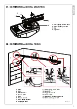
Страница 9: ...3 Rail 4 Cogwheel 9 Self tapping screw 6x15 10 Bent arm 11 Support bracket 12 Screw 8x20 13 Gearmotor mounting bracket 14 Rail mounting bracket 1 Wall 2 Door 3 Wall bracket 4 Screw 6x80 5 Rail 6 Screw...

Страница 10: ...to close String Clutch joint Rail WHEN POWER RECOVERS Give a start command using the transmitter or other fixed commands the trolley clutch engages automatically D4 MANUAL RELEASE FROM OUTSIDE If the...

Страница 11: ...k the clutch and gently move the door to closing position b Power the garage door opener the courtesy light turns on the display shows a 0 rotating clockwise and the control unit beeps once Press P an...

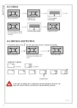
Страница 12: ...o save E4 OBSTACLE DETECTION The factory value set is the end user should never change this setting Press to set 4 Press P then use and to increase or decrease the value Press P to save SENSITIVITY LE...

Страница 13: ...5 Press P and use and to change the value Press P to save E6 DOOR OPENED ALERT This function beeps within 10 minutes if the door is left open The factory setting is 0 function deactivated to activate...

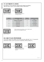
Страница 14: ...seconds 90 seconds 2 minutes 2 5 minutes 3 minutes 3 5 minutes 4 minutes When automatic closing feature is set an alarm sound will be sent all the waiting time long Press P to save E8 2000 CYCLES PER...

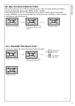
Страница 15: ...d giving a start command with the transmitter the door will operate step by step OPEN STOP CLOSE When the function is set to 1 activated giving a start command with the transmitter during OPENING the...

Страница 16: ...e Additional transmitters can be saved repeating the same procedure Press and hold S until display shows 0 on the left side Hold S as long as 0 disappears Now all transmitters previously saved have be...

Страница 17: ...14 BBU AC24V MOT GND DISPLAY E LOCK STANDBY HOLZER TRIP SW LIGHT WIRING DIAGRAM START CABLED COMMANDS BLINKER AERIAL WIRE PHOTOCELL OR SAFETY EDGE N C contacts FACTORY WIRING rev02_19...

Страница 18: ...2 have to be wired to GND through NC contacts Therefore bridge the RX NC contact to GND and wire the other NC contact to IR1 or IR2 EMERGENCY PUSH BUTTON START STOP AND BLINKER contacts It is possible...

Страница 19: ...nto the black membrane and pass it through the special slot on the door fig B Fix the inox cable to the lock release fig C1 or to the handle fig C2 Make sure the cable is properly tightened so as to u...

Страница 20: ...s shown in fig B and fix it on the door beside the adapter Insert the inox cable into the black membrane and pass it through the special slot on the door fig C Fix the inox cable to the lock release f...

Страница 21: ...release is fitted inside the gap fig I Place the boomerang bracket provided witht the arm adapter leaving the string through as shown in fig L Tighten the 5 screws and fix the bracket to the trolley...

Страница 22: ...ly c Periodically check that door opens and closes at the correct heights and that springs have sufficient thrust to lift the door Lubricate mechanical gears regularly if necessary If power failure oc...

Страница 23: ...heck photocells wiring p 15 Incorrect photocell wiring Check the safety microswitch is not crushed Release the microswitch that may have been trapped Crushed safety microswitch Incorrect photocell wir...

Страница 24: ...CE 2014 35 UE LVD The product also complies for the applicable parts to the following directives and standards EN12453 EN12604 EN55014 1 EN55014 2 EN61000 6 1 EN61000 6 3 EN 60335 1 EN 60335 2 103 EN...

Страница 25: ...nts may contain hazardous waste They must thus be removed and turned into licensed firms for their disposal Before acting always check the local laws on the matter 22 rev02_19 Proteco srl Via Neive 77...

Страница 26: ...rev02_19...

Отзывы: